Lock in Amplifier on LabVIEW FPGA
- Subscribe to RSS Feed
- Mark as New
- Mark as Read
- Bookmark
- Subscribe
- Printer Friendly Page
- Report to a Moderator
Products and Environment
This section reflects the products and operating system used to create the example.To download NI software, including the products shown below, visit ni.com/downloads.
- CompactRIO/SingleboardRIO
Hardware
- NI RIO
Driver
Code and Documents
Attachment
Overview
This example uses the LabVIEW FPGA to implement a phase locked loop, mixer, and low pass filter.
Description
A Lock-in Amplifier is an instrument that can detect the amplitude and phase of sinusoidal signal with known frequency in an extremely low signal to noise environment. This example shows how to use LabVIEW FPGA to build a lock-in amplifier on a CompactRIO. The following diagram illustrates the principle of a Lock-in Amplifier. A Phase Locked Loop (PLL) will lock to the frequency in the reference channel and generate a clean sinusoidal wave. It then multiplies the signal in the mixer, modulating the weak sinusoidal wave in signal channel to DC frequency. After a low pass filter, the amplitude and phase of weak sinusoidal wave can be revealed.
. 
In this example, PLL, mixer and low pass filter are implemented by LabVIEW FPGA. The performance of FPGA based lock-in amplifier can be summarized below:
Hardware | cRIO 9104 NI 9233 |
Resolution | 24 bit |
Sampling Rate | 50kHz, limited by 9233 |
Time Constant | 1ms to 20ks |
Filter Rolloff | 20dB, 40dB, 60dB, 80dB |
Noise Level | <-100dB, determined by 9233 |
Dynamic Reserve | >100dB |
For detailed description on the principle of lock-in amplifier, see Principle of Lock in amplifier.pdf in attached file. For detailed description on how to setup the example, including hardware and software requirements, see LIA_IPnet_Readme.pdf in attached file. A simplified version of Lock-in Amplifier is also available on the Xilinx academic SPARTAN 3E XUP Board.
Steps to Implement or Execute Code
- Download the relevant code for your LabVIEW version
- Open LIA.lvproj
- Retarget for your device or create your own target and move all the VIs and resources to the new target
- LIA_FPGA.vi is the top FPGA VI, please move the associated files if you are creating a new target
- Compile LIA_FPGA.vi by opening the VI and clicking the run button
- Open host.vi under My Computer target
- You can control sampling frequency of AD converter, decimation factor of first and second CIC filter, number of stages (1 or 2) and decimation factor of MA filter, or the center frequency of PLL in the GUI
- Run the VI and press the Start button
Requirements
Software
LabVIEW 8.6 "or compatible" (See note at the end of the document)
LabVIEW FPGA 8.6 "or compatible" (See note at the end of the document)
Hardware
Spartan3E Academic Board
Signal Generator or Other Signal Source
Voltage Offset Circuit for Analaog Input Range
Steps to Implement or Execute Code
Note:
1, Please download LIA_IPnet.zip if you are using LabVIEW FPGA 8.6.
2. Please download LIA_IPnet_LabVIEW2009.zip if you are using LabVIEW FPGA 2009.
3. If you are using cRIO DSA modules other than cRIO-9233, you need to change the cRIO module under the FPGA target, update the Data Rate control in FPGA VI and Host VI, and modify the NILIA_9233fs.vi to make the sampling frequency mapping correct for your module.
4. New projects for lock-in amplifier on Xilinx SPARTAN-3E XUP Starter Board are added. Because of fewer resources on SPARTAN-3E FPGA chip, this lock-in amplifier is a lite version, compared with the implementation for cRIO.
- Please download LIA_spartan86.zip if you are using the starter board with LabVIEW FPGA 8.6
- Please download LIA_spartan2009.zip if you are using the starter board with LabVIEW FPGA 2009
5. New project for lock-in amplifier on sbRIO-9642 is added. The key part of the lock-in amplifier is the same as the one for SPARTAN-3E FPGA chip. The difference is that it uses the I/O nodes offered by NI. The project is a code reference for sbRIO users to get started with the lock-in.
Additional Information or References
**This document has been updated to meet the current required format for the NI Code Exchange. For more details visit this discussion thread**
Example code from the Example Code Exchange in the NI Community is licensed with the MIT license.
- Mark as Read
- Mark as New
- Bookmark
- Permalink
- Report to a Moderator
Version 6 does not compile in LabVIEW 2009, because several nodes are incorrectly configured for inside single-cycle Timed Loop execution. Workaround is to manually configure each node to execute outside the single-cycle Timed Loop.
- Mark as Read
- Mark as New
- Bookmark
- Permalink
- Report to a Moderator
Hi, JLewis,
Thanks for your nice catch. LIA_IPnet_LabVIEW2009.zip is added for LabVIEW FPGA 2009 users.
- Mark as Read
- Mark as New
- Bookmark
- Permalink
- Report to a Moderator
well done!
Could you please add the simplified version of Lock-in Amplifier available on the Xilinx academic SPARTAN 3E XUP Board?
- Mark as Read
- Mark as New
- Bookmark
- Permalink
- Report to a Moderator
Done.
- Mark as Read
- Mark as New
- Bookmark
- Permalink
- Report to a Moderator
hello there,
do you have the summarized performance data for the lite version for the spartan3E? (Time constant, Dynamic Reserve...)
greetings
Florian
- Mark as Read
- Mark as New
- Bookmark
- Permalink
- Report to a Moderator
Sorry. I don't have any at hand.
Thanks,
Richtian
- Mark as Read
- Mark as New
- Bookmark
- Permalink
- Report to a Moderator
hi,
I'm an AE in NI China. Is it possible to realize the lock in amplifier in FlexRIO+576X? I mean I want to increase the sample rate. If it is possible, maybe we can deal with signal with higher frequency.The customer wants to realize the lock-in amplifier to measure the signal which is about 80MHz.
Thanks.
Yu Sun
Yu Sun
NISH
- Mark as Read
- Mark as New
- Bookmark
- Permalink
- Report to a Moderator
I have a similar request for signal frequency around 50 MHz
- Mark as Read
- Mark as New
- Bookmark
- Permalink
- Report to a Moderator
hi,
http://nitalk.natinst.com/docs/DOC-48560
“we achieve 8MHz input sampling frequency at 40MHz FPGA clock rate”
Best regards!
National Instruments China 美国国家仪器(NI)有限公司
Yu Sun 孙瑜 | yu.sun@ni.com | Applications Engineer | http://www.ni.com
Tel: 010-82625966 ext: 8011 | 传真:010-82862099 | 地址: 北京海淀区中关村科
学院南路2号,融科资讯中心A座9层
From: Mitss <web.community@ni.com>
To: freedomxn <yu.sun@ni.com>
Date: 2012/07/01 21:19
Subject: Re: - Lock in Amplifier on
LabVIEW FPGA
Community
Lock in Amplifier on LabVIEW FPGA
new comment by Mitss View all comments on this document
I have a similar request for signal frequency around 50 MHz
Reply to this email to respond to Mitss's comment.
Yu Sun
NISH
- Mark as Read
- Mark as New
- Bookmark
- Permalink
- Report to a Moderator
Would it be possible to add a version for sbRIO boards (e.g., sbRIO9642) and LabVIEW 2011SP1?
Thanks.
- Mark as Read
- Mark as New
- Bookmark
- Permalink
- Report to a Moderator
I think you can just use the LIA_spartan86 version. Because sbRIO9642 is using Spartan-3 FPGA and having 16bit input data bit width. Just to replace those I/O nodes with the nodes for sbRIO9642 should get you a working version.
- Mark as Read
- Mark as New
- Bookmark
- Permalink
- Report to a Moderator
Hi Support!
My question is similar to pbuerki... but I'm working on
sbRio9631 and Labview 2010 SP1. I've tried to adapt all the
versions listed on this site to my device sbRio unsuccessfully,
after you post above I'm just working on the LIA_spartan86
version without good results. You've writen to us just replace
the I/O nodes, I tried it, but I don't have a working
application. Could you give me more details about that? We have
a unsigned int type on input of the sbRio devices and the lock
in works with boolean array, how can you adapt the ADC sbvi to
work with boolean array data type? Do I need to use the Reverse
1D array vi?
And about the host application:
- Does this application work at 250kS/s?
- Do I need to calibrate the signal from FPGA device using LSB
Weight (+/- 10V range) an Offset (+/- 10V range) parameters?
Find in attached the screenshot of the my adapted version.
Please, could you insert a working application to sbRio9631? It will be very helpful.
Please, reply as soon as possible.
Thank you for yor attention.
Best regards.
- Mark as Read
- Mark as New
- Bookmark
- Permalink
- Report to a Moderator
According to Dasosa's diagrams, I notice that I didn't make it clear about the AI part. The Spartan-3E Starter Board is not an NI product so that the codes to do analog acquisition is a little bit strange. Actually, with NI sbRIO-9631 and sbRIO-9642, if you use ModA (NI 9205) to do AI, it's much simpler and straightforward. Please refer to the diagram below, which is a VI snippet.
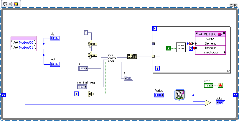
Since NI 9205 is a 16-bit module, you can directly cast the I16 to an <+/-, 16, 1> fixed-point data type and then use the LIA codes. Besides, the sampling rate is specified by the Period control. Remember to specify this control before starting data acquisition. And, you should set the sampling rate properly for both host side and FPGA side.
Besides, what's important is to correctly specify which channel is the reference channel.
As for the two questions from Dasosa, here are my comments.
- Does this application work at 250kS/s?
According to NI 9205 documentation (http://sine.ni.com/nips/cds/view/p/lang/en/nid/208800), the module has 16 bit resolution and 250kS/s aggregate sampling rate. That's to say, if you are using two AI channels, it should be 125kS/s sampling rate per channel. BTW, the ticks indicator in the diagram above tells you the actual sampling rate.
- Do I need to calibrate the signal from FPGA device using LSB Weight (+/- 10V range) an Offset (+/- 10V range) parameters?
I don't think you need to calibrate the signal for Offset on the FPGA. But, if you need the actual amplitude value, of course, you need the LSB Weight to do the math on the host side.
BTW, I'm sorry that I don't have such an sbRIO at hand so that I cannot provide a full project.
Thanks,
Richtian
- Mark as Read
- Mark as New
- Bookmark
- Permalink
- Report to a Moderator
Hi Richtian!
NI's web support is always helpful and fast! Thanks a lot for your help!
What's the meaning of the 2 ticks in diagram above?
How can I set the sample rate properly for both host side and FPGA side?
I've worked on lock-in application, now I have it working to low frequencies (Vin = 10kHz and sample rate = 50kS/s). It's great, but I need to improve to Vin = 22kHz and sample rate = 125kS/s or another frequency value to detect the phase to 22kHz. Why the PLL can't detetc the frequency of the reference signal when I change the sample rate to values higher than 50kHz.
freedomxn sad: “we achieve 8MHz input sampling frequency at 40MHz FPGA clock rate”. How can I do it too? The link is broked.
Thank you!
- Mark as Read
- Mark as New
- Bookmark
- Permalink
- Report to a Moderator
Hi, Dasosa,
Actually, only one Loop Timer node is needed for the data acquisition loop. The Counter (Ticks) control and its related Loop Timer node is unnecessary, which you can remove from the diagram. And you just need to use the Period control for the loop rate control. As for the ticks indicator, it tells you the actual loop rate that the while loop achieves. Sometimes, because of the many computation you want to apply for AI signals, your loop rate could be slower than the reqested loop rate.
I just submit a project based on sbRIO-9642 FYI. Based on my experience, there are several reasons why your codes don't work at 125kHz.
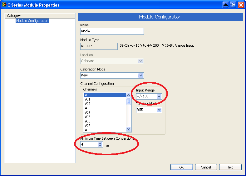
1. Check the 9205 module configuration dialog to make sure that you specify 4us conversion time for the module. The default value is 8us, which can only give you 62.5kHz sampling frequency for LIA.
2. The modified version as I showed before from Spartan-3E project cannot hit the 125KHz. Because of the computation, it only hits about 108kHz. However, you can refer to the new sbRIO project where two feedback nodes are inserted to solve the issue.
BTW, since the 9205 allows you to specify different input range, this range becomes a parameter on the host side. To get more accurate amplitude result, you might try to use LSB weight from the module when calculating the actual amplitude on the host side.
As for the 8MHz input sampling frequency at 40MHz FPGA clock rate, it's something we are trying.
Thanks,
Tianming
- Mark as Read
- Mark as New
- Bookmark
- Permalink
- Report to a Moderator
I would like to modify the code (LIA_IPnet) for a different FPGA card(NI PXI-7852R). Any suggestions?
Thank you,
Massimo
- Mark as Read
- Mark as New
- Bookmark
- Permalink
- Report to a Moderator
Hi, Massimo
You should focus on the data acquisition loop. Make sure that you are sampling at the expected sampling rate and feeding the reference signal and the actual signal to the right channel.
Please note that the way to sample signal on PXI-7852R is different from that of cRIO-9233. Hence,
1. On FPGA VI, you should use Loop Timer to control the sampling rate.
2. On the host side, you need to handle the 9233fs.vi. Actually, the output of this VI is the actual sampling frequency. Just replace the VI with the actual sampling frequency value.
Thanks,
Richtian
- Mark as Read
- Mark as New
- Bookmark
- Permalink
- Report to a Moderator
Hi Richtian,
thank you very much for the suggestions, I will try them and let you know!
thanks again
Massimo
- Mark as Read
- Mark as New
- Bookmark
- Permalink
- Report to a Moderator
Hi everybody,
I have two questions:
1)
I have adopted the LIA using a NI9239 50kS/s and using reference sine wave generated on the host that I feed to the target. It works. However, I have one dump question: Do the I and Q values that are streamed from the target to the host correspond to a single sample of the signal array (or a mean DC value)? Im other words, if I use a time constant of 100 ms at 50 kS/s, do I have to wait until there will be 5000 I and Q values on the host in order to see the complete signal? Given a while loop rate on the host of 10 ms, this takes almost a minute, quote
long. I could try to use a FIFO to give me these 5000 values at once. Thank you for your input !
2) Does anyone have some performance values, I mean SNR? While the LIA in principal works and shows the expected behavior when parameters are changed, I get a better SNR using simple AC coupling without any lock-in or digital filtering at all!
More concrete: I have a laser beam, modulated with a 1 kHz sine generated on the host (just an array length 50, 1 period) and output using an analog output module to an amplitude modulator that modulates the laser beam. The reference is just a copy of the modulation signal array, which is written to the fpga and fed into the LIA, which is the version for the 24 bit ADC downloaded from this site.
Now, I quantify how stable the DC signal is. I do this on the host by taking the ratio between the mean of a couple of mean values (each say 600 samples) by their standard deviation. I get no better than 1000. When I do NOT use any LIA, but only compute the ratio of the mean of a couple of RMS values of the digitized signal I easily achieve 3000. I need 10000 however. The motivation for us using a LIA is to get away from flicker noise (and mechanical shocks) which screws our DC measurement and decreases the SNR we would be achieving without flicker noise by a factor of 100.
Am I doing something wrong?
Thank you!!
- Mark as Read
- Mark as New
- Bookmark
- Permalink
- Report to a Moderator
Allright, I found a problem that quite likely is responsable for the poor performance of the lock-in implementation in Labview. I directly fed the analog output signal into the ADC and defined this to be the science signal. The science signal, when sampled by the ADC, is slightly (< 0.1 %) varying in amplitude. This is an effect introduced by the ADC itself. When in the PSD stage this signal is multiplied with a perfect sine wave at the reference frequency, then there are periodic variations in amplitude being introduced, i.e., a sort of artificial noise. It is especially pronounced using the NI9239 with a period of ca. 1 s and less strong using the 1 MS/s ADC NI 9223 with a 20 ms period. Due to the higher frequency of this "amplitude modulation" I get much better results using the latter.
- Mark as Read
- Mark as New
- Bookmark
- Permalink
- Report to a Moderator
What changes would be necessary so that the above code could use an arbitrary (i.e. multi-frequency) ref. signal to demodulate with?
Thanks
- Mark as Read
- Mark as New
- Bookmark
- Permalink
- Report to a Moderator
According to the theory, I think you cannot use an arbitrary ref. signal. The codes above only support pure sine/square wave as reference signal. If you have multiple frequencies as ref. signal, probably, you have to handle those as multi-channel ref. signals. This is my understanding.Thanks.
- Mark as Read
- Mark as New
- Bookmark
- Permalink
- Report to a Moderator
Hi,
I am Naveed ,from south korea,
May I have Lock-In Amplifier code for Labview version 10?
- Mark as Read
- Mark as New
- Bookmark
- Permalink
- Report to a Moderator
Hey, Naveed, if you have LabVIEW 2010, you can try to open the LabVIEW 2009 above directly in the LabVIEW 2010.
- Mark as Read
- Mark as New
- Bookmark
- Permalink
- Report to a Moderator
I am trying to implement this code on a cRIO 9022 with the input coming from an NI 9215. My issue is that i cannot set the data rate as it is stuck at 100KS/s. I've tried removing most of the data rate parts and changed it to 100KS/s but it seems like its not sampling at a consistant rate. I can get the thing to run but i do not get a lock and the locked frequency just keeps increasing.
Also on the fpga vi, the frequeny detector always outputs 0 even though I probe it and there is a value on the wire, and I and Q give me value if I run the VI by tself but when run through the host I and Q stay at 0 on the host.
- Mark as Read
- Mark as New
- Bookmark
- Permalink
- Report to a Moderator
To use 9215 on FPGA, you have to use the Loop Timer node to decide the sampling rate.
- Mark as Read
- Mark as New
- Bookmark
- Permalink
- Report to a Moderator
Hello I am trying to work on a lockin amplifier builtin labview using NI USB 6210. But I am unable to understand the logic of lockinPLL.vi. Could anyone help me out to understand how it works? Or refer any source to learn how lockin amplifier using labview works.
- Mark as Read
- Mark as New
- Bookmark
- Permalink
- Report to a Moderator
Seems that you are using NI Lock-in Start Up kit. There should be an NILockinStartupKit.doc in the package.
- Mark as Read
- Mark as New
- Bookmark
- Permalink
- Report to a Moderator
I have PXI4462andPXI5406 I want use 5406 output the waveform and 4462 for input to make a lock-in amplifier ,but it do not work, the phase is drift, I do not know why, and could send me the NI Lock-in Start Up kit, My Email address is sxg_buaa@163.com. thank you and Look forward to your reply.
- Mark as Read
- Mark as New
- Bookmark
- Permalink
- Report to a Moderator
Hi all
I following problem, I have to use Pll to synchronize motor speed with a external frequenz von 333hz . I don't really unterstand how to use the 3 phase PLL VI to solve this problem, because I have square or pulse wave signal instead of sine wave and I have to come out with a PWM duty cycle value in tick or us (1khZ frequenz) to drive the Motor. Is there any explanation about how to do that
Thx
- Mark as Read
- Mark as New
- Bookmark
- Permalink
- Report to a Moderator
Hi all,
I am trying to make a LIA on NI-MyRIO, which code is better to use as a starting code, and what should i change in it?
Thank you,
- Mark as Read
- Mark as New
- Bookmark
- Permalink
- Report to a Moderator
Hi all,
which is better for lock-in amplifier applications:
to use a DSA board (like PCI-4462), or a combined let's say sbRIO 9607 + 9223 16 bits, 1MS/s/CH Module, and use the FPGA LIA code??
I want to measure signals with reference up to 100 KHz.
Hope somebody can advise me,
Thx
- Mark as Read
- Mark as New
- Bookmark
- Permalink
- Report to a Moderator
Hi everyone,
Thank you very much for this nice helpfull code!
I am trying to implement LIA code on my project. The purpose of the setup is to actuate a piezoelement that will produce a mechanical vibration at desired frequency (few nanometers at few dozens of hertz). The vibration is measured with an interferometer over a range of few millimeter.
This interferometer gives me AquadB signal with a resolution of 512pm at high frequency (1kHz in my case) over a range of of 50mm (which correspond to approx 100^6 tops of the AquadB signal), .
Therefore, I have change the code to use I32 type of input to my signal, and change the multiplier in the demod VI to output 64,3 bits.
The ref signal is self generated in the code so far, and is still a 24,1 number.
My problem now is that the amplitude given by the LIA is dependant of the mean value of my signal. It is correct when the average position is 0, but it is not when my signal is centered around an other value (that can be up to 10^6 in my case...)
I have checked the output of the demod VI and it seems all right. I am wondering if my problem comes from the cascades CIC filters, shift Arithmetics and MA vis. I am having a hard time to understand what they do exactly (cut off frequency, resampled rate, MA lenght...). They seems to have been designed to deal with I64 numbers, even when the output of the demod VI is 32 bits.
On the other hand, the rational resampler express VI, and most of the math functions of the FPGA palettes are given to 32 bits...
I suppose that some bits are lost in the cascaded add functions, but i can't see exactly where...
Any help will be welcome!
Regards,
Matthieu
- Mark as Read
- Mark as New
- Bookmark
- Permalink
- Report to a Moderator
To decide whether you should use DAQmx or FPGA, It depends on how many latency you can accept or not.
If you need real time response, you need FPGA.
If you don't need it and you have to just log the date, you can use DAQmx.
For DAQmx, I created example code before, please refer it.
https://forums.ni.com/t5/Example-Program-Drafts/Lock-in-amplifier-with-DAQmx/ta-p/3698819
Also you should think about dynamic range of the AD converter to gain ideal S/N for the signal you want to see.
