Frequency Shift Keying Digital Modulation with LabVIEW
- Subscribe to RSS Feed
- Mark as New
- Mark as Read
- Bookmark
- Subscribe
- Printer Friendly Page
- Report to a Moderator
Code and Documents
Attachment
Overview
These example VIs examine the Frequency Shift Keying (FSK) digital modulation scheme.
Description
Fundamentally, digital modulation requires changing characteristics of the carrier wave over time. Each change results in a sine wave with a different phase, amplitude, or frequency than before. As a result, different “states” of the sine wave are referred to as symbols which represent some digital bit pattern. In this exercise, we will construct LabVIEW VIs that transmit and receive a digital bit stream using FSK.
Steps to Implement or Execute Code
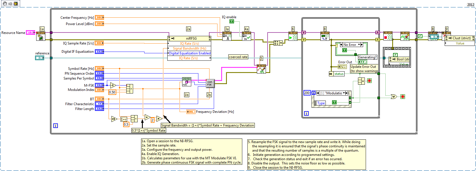
Generation
1a. Open a session to the NI-RFSG.
1b. Calculate parameters for use with the MT Modulate FSK VI.
2a. Set the sample rate.
2b. Generate phase continuous FSK signal with complete PN cycle.
3. Configure the frequency and output power.
4. Enable IQ Generation.
5. Resample the FSK signal to the new sample rate and write it. While doing the resampling it is ensured that the signal's phase continuity is maintained and that the resulting number of samples is a multiple of the quantum.
6. Initiate generation according to programmed settings.
7. Check the generation status and exit if an error has occurred.
8. Disable the output. This sets the noise floor as low as possible.
9. Close the session to the NI-RFSG.
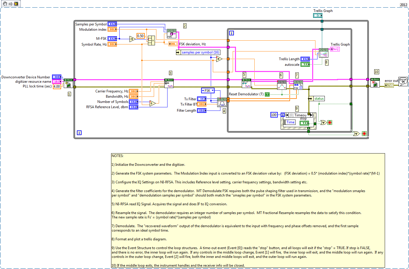
Acquisition
1. Initialize the Downconverter and the digitizer.
2. Generate the FSK system parameters. The Modulation Index input is converted to an FSK deviation value by: (FSK deviation) = 0.5* (modulation index)*(symbol rate)*(M-1).
3. Configure the IQ Settings on NI-RFSA. This includes Reference level setting, carrier frequency settings, bandwidth setting etc.
4. Generate the filter coefficients for the demodulator. MT Demodulate FSK requires both the pulse shaping filter used in transmission, and the "modulation samples per symbol" and "demodulation samples per symbol" should both match the "samples per symbol" in the FSK system parameters.
5. NI-RFSA read IQ Signal. Acquires the signal and does IF to IQ conversion.
6. Resample the signal. The demodulator requires an integer number of samples per symbol. MT Fractional Resample resamples the data to satisfy this condition. The new sample rate is Fs' = (symbol rate)*(samples per symbol)]
7. Demodulate. The "recovered waveform" output of the demodulator is equivalent to the input with frequency and phase offsets removed, and the first sample corresponds to an ideal symbol time.
8. Format and plot a trellis diagram.
9. Use the Event Structure to control the loop structures. A time-out event (Event [0]) reads the "stop" button, and all loops will exit if the "stop" = TRUE. If stop is FALSE, and there is no error, the inner loop will run again. If any controls in the middle loop change, Event [1] will fire, the inner loop will exit, and the middle loop will run again. If any controls in the outer loop change, Event [2] will fire, both the inner and middle loops will exit, and the outer loop will run again.
10. If the middle loop exits, the instrument handles and the receiver info will be closed.
Requirements
Software
LabVIEW 8.6 or later
RFSA and RFSG drivers
Hardware
Any NI RF hardware that uses RFSA and/or RFSG
VI Snippets
**This document has been updated to meet the current required format for the NI Code Exchange. For more details visit this discussion thread**
Example code from the Example Code Exchange in the NI Community is licensed with the MIT license.
