Look-up Table for Sinusoidal (V/f) Control of a Brushless DC Motor
- Subscribe to RSS Feed
- Mark as New
- Mark as Read
- Bookmark
- Subscribe
- Printer Friendly Page
- Report to a Moderator
Products and Environment
This section reflects the products and operating system used to create the example.To download NI software, including the products shown below, visit ni.com/downloads.
- Motion Control
Hardware
- LabVIEW
Software
Code and Documents
Attachment
Overview
This block of FPGA code computes three PWM outputs for the three legs of a 6-FET bridge to produce a 3-phase sinusoidal voltage to drive a brushless DC (BLDC) motor.
Description
There are various ways to control a brushless motor (6-phase control, sinusoidal control, field-oriented control, etc). The simplest method, 6-phase control, involves energizing the 6 FETs in the motor driver bridge in an on/off manner dependent on the position. Because there are 6 regions of the motor's windings, there are six steps in this control algorithm (hence the name). Next in complexity of BLDC motor control is the sinusoidal or V/f (voltage-over-frequency or voltage-over-hertz) controller which uses three PWM values to generate an approximation of 3-phase current.
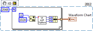
The block takes an input that represents the angular position of the BLDC motor between 0 and 1023 which corresponds to a theta value between -pi and pi. The outputs of the block are three values for a 9-bit (0 to 511) PWM. The PWM values represent the "on" time in a PWM with a period of 512.
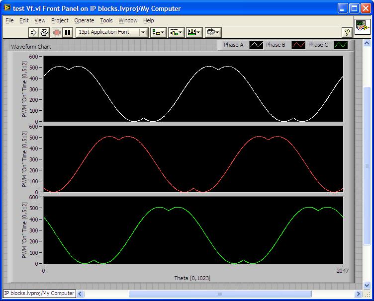
To implement this controller, the PWM values get sent to the high-side FETs for each leg of the 6-FET bridge. The low-side FET is always the opposite digital value of the high-side FET. To prevent shoot-through it is important to delay the rising edge of the PWM signal to account for FET and cable dynamics. Sending the three FET values generated by this VI to a bridge designed for BLDC control will yield a very good approximation of a sinusoidal, 3-phase current to drive a BLDC motor. The PWM values for two rotations can be seen in the figure below. The attached files include the VI to produce the 3 PWM values, a test VI and the image embedded here.
Requirements
Software
LabVIEW 8.6 "or compatible"
LabVIEW FPGA 8.6 "or compatible"
Steps to Implement or Execute Code
1. Download and extract LUT Example.zip
2. Open test Vf.vi
3. Run test Vf.vi
VI Snippets
Additional Information or References
**This document has been updated to meet the current required format for the NI Code Exchange. For more details visit this discussion forum.**
Example code from the Example Code Exchange in the NI Community is licensed with the MIT license.
