Description
Description-Separate-1Overview
This example shows how PID control can be implemented in a simulation environment using the LabVIEW Control Design and Simulation Module.
Description
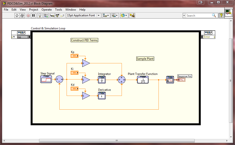
The example VI is a standard single-input single-output control system running in a simulation environment. The controller used is parallel PID and the plant in this case is a basic transfer function example. This example is intended to be used as a reference for design. The controller, plant, and other components can be easily expanded.
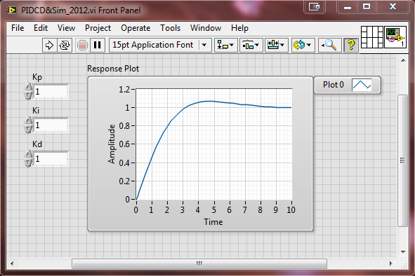
The user is able to change the PID gains on the front panel to see the affect on the closed-loop system. User can also change the plant model by double-clicking on the Transfer Function VI and modify the numerator and denominator accordingly.
Steps to Implement or Execute Code
- Open the corresponding VI that matches with your development version.
- You're all set, go ahead and run the VI!
- You can modify VI further by adding simulation components from the subpalette: Control Design & Simulation > Simulation found in the LabVIEW functions palette
Requirements
Software
LabVIEW Development Environment 2010 or higher
LabVIEW Control Design and Simulation Module 2010 or higher
Hardware
N/A
Additional Notes
Here are some additional resources:
LabVIEW Control Design and Simulation Download
PID Control
Closed Loop Motor Control with LabVIEW
**This document has been updated to meet the current required format for the NI Code Exchange. For more details visit this discussion thread**
Description-Separate-2
