Update Multiple Analog Output DAQmx Channels On-The-Fly
- Subscribe to RSS Feed
- Mark as New
- Mark as Read
- Bookmark
- Subscribe
- Printer Friendly Page
- Report to a Moderator
Products and Environment
This section reflects the products and operating system used to create the example.To download NI software, including the products shown below, visit ni.com/downloads.
- Data Acquisition (DAQ)
Hardware
- LabVIEW
Software
- NI DAQmx
Driver
Code and Documents
Attachment
Overview
This example code shows how one might program a scalable number of analog output channels using NI-DAQmx to generate different waveforms or frequencies.
Description
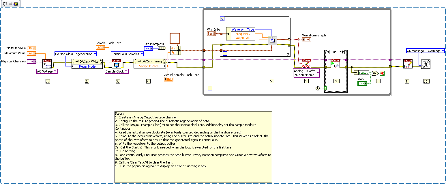
This example demonstrates the ability of the NI-DAQmx API to take an incoming array of information and split it into individual parts that can be applied to different analog output channels. The sampling frequency of the waveform generation is set by the sampling frequency used for outputting data samples from the card so the chances of filling the output buffer are eliminated. The output waveforms have the ability to be updated during execution since the creation of the waveforms is done in the same loop as the analog write function. This example uses Non-Regeneration, meaning new data is constantly being written to the buffer (as opposed to looping the same data over and over again). This gives two major benefits:
1. We can generate frequencies that are non-integer divide downs of the sample clock,
2. We can update waveform properties on the fly.
Requirements
Software
LabVIEW 8.6 or compatible
DAQmx 9.5 or comaptible
Hardware
Any Multifunction DAQ card or Analog Output Card which is supported by your version of NI-DAQmx
Steps to Implement or Execute Code
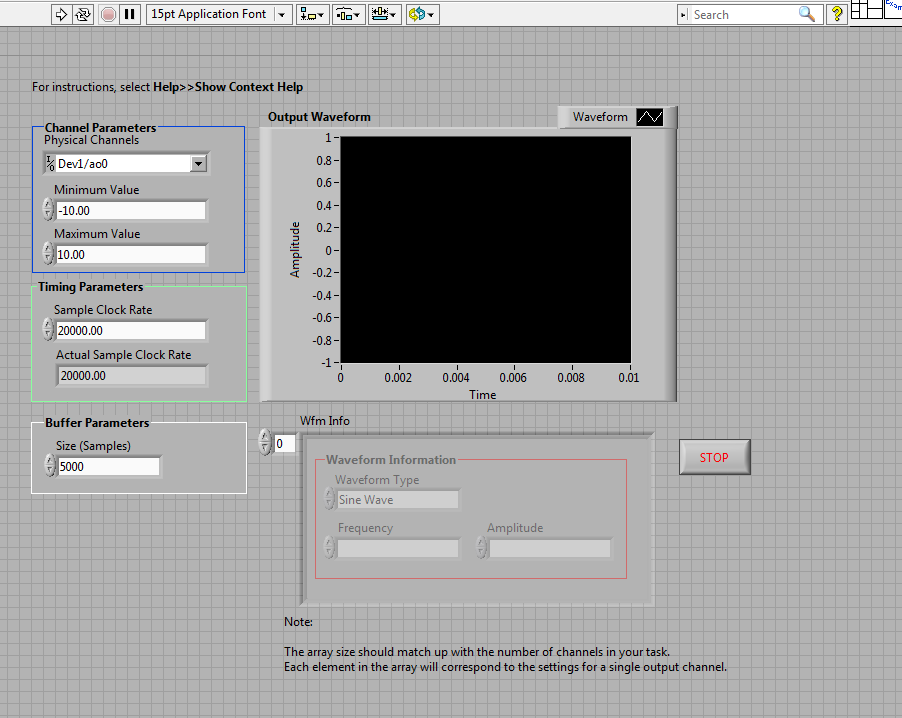
- Select which device you want to use for the example and configure the following parameters on the front panel:
- Physical Channels
- Minimum and Maximum Value
2. Configure the following timing parameters:
- Sample Clock Rate
3. Configure the buffer parameter of Size(Samples)
4. Enter the Waveform characteristics of each of the waveforms you want to generate in the Wfm Info Array control
5. Run the VI
Additional Information or References
Block Diagram
Front Panel
**This document has been updated to meet the current required format for the NI Code Exchange.**
Example code from the Example Code Exchange in the NI Community is licensed with the MIT license.
- Mark as Read
- Mark as New
- Bookmark
- Permalink
- Report to a Moderator
Any LabVIEW 2009 users might consider modifying the code to use a parallel for loop to generate the waveforms.
- Mark as Read
- Mark as New
- Bookmark
- Permalink
- Report to a Moderator
The version that Updates Phase is a little messy--I had originally used a feedback node which got butchered when I saved back to LV 8.2.
If you have any questions about the code don't hesitate to post.
- Mark as Read
- Mark as New
- Bookmark
- Permalink
- Report to a Moderator
Went ahead and saved a version in LV 2010 that uses the feedback node instead of shift register.
- Mark as Read
- Mark as New
- Bookmark
- Permalink
- Report to a Moderator
Great example for on-the-fly analog output waveform generation.
Thanks for sharing the example.
