- Document History
- Subscribe to RSS Feed
- Mark as New
- Mark as Read
- Bookmark
- Subscribe
- Printer Friendly Page
- Report to a Moderator
- Subscribe to RSS Feed
- Mark as New
- Mark as Read
- Bookmark
- Subscribe
- Printer Friendly Page
- Report to a Moderator
Course Linkage: Linear Circuit Analysis >> Resistive Circuits >> Parallel Resistors
Measurement Techniques: ELVISmx DMM (ohmmeter)
<hr width=”75%”>
Introduction
Overview: Two-terminal devices connected together in parallel share a common pair of terminals. Parallel resistors offer multiple paths for current between the two terminals thereby decreasing the effective resistance between the terminals. Resistors connected in parallel behave as a single equivalent resistor whose conductance is the sum of the individual resistor conductances.
Objectives: In this mini-lab you will:
- Learn about resistor color codes
- Measure the resistance of individual resistors
- Compare measured resistance to nominal value
- Predict the equivalent resistance of parallel-connected resistors
- Compare measured equivalent resistance to expected values
Equipment
- NI myDAQ
- Breadboard
- Connecting wire
- Resistors, ¼-W 5% carbon film: 10K (two), 33K (two), 47K (two)
Deliverables
- Submit your work in the form of a homework set problem or lab notebook entry according to the requirements of your instructor
- Submit your work for each underlined boldface item, and clearly label the item with its section letter and task number
A. Experience parallel-connected resistors by measurement
NOTE: Proceed directly to Step 10 if you have already completed the myDAQ mini-lab Equivalent Resistance I – Series and your breadboard still contains the same resistors that you measured earlier; you will need those measurements for this mini-lab.
- Study the short article Resistor Color Codes to learn how to read the nominal value encoded in the color bands that encircle a resistor. For example, the 10K resistor has the color code “orange-orange-orange” = 33 x 103 = 33 kW.
- Record the color bands for the 10K and 47K resistors.
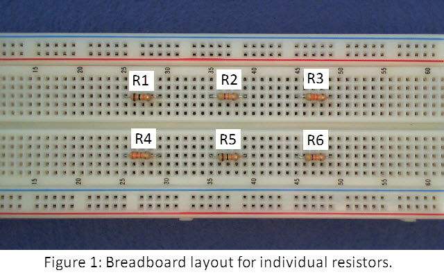
- Place the six resistors on your breadboard as shown in Figure 1. Use the same hole spacing to match the wiring that will be added later.
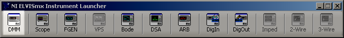
- Start the ELVISmx Instrument Launcher and click “DMM.” Choose the ohmmeter instrument (the “ohm” symbol, capital omega), select autoranging (choose “Auto” for “Mode”) and click the green “Run” button:
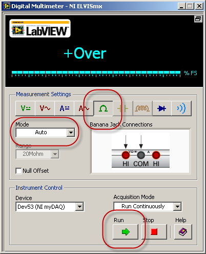
- Connect the DMM probes to the ohmmeter side (red volt-ohm and black COM jacks) as shown on the ELVISmx DMM “Banana Jack Connections” graphic.
- Touch the DMM probe tips together to ensure that the ohmmeter properly reads zero or at most a fraction of an ohm. The probe cables have negligible resistance compared to the resistors used in this mini-lab.
- Measure and record the resistance of each of the resistors R1 through R6.
- Create a data table with four columns: resistor label, nominal value (i.e., the value indicated by the color code), measured value, and percentage difference from nominal. Calculate the last column as ((Rmeasured – Rnominal)/Rnominal) x 100%.
- Report the largest percentage difference and whether or not it falls within 5% of the nominal value; this is the significance of the gold 5% tolerance band on the resistor.
- Connect the resistors as shown in Figure 2:
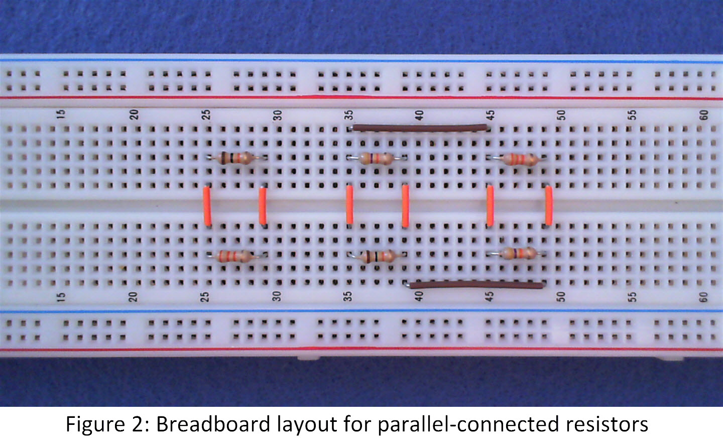
- Measure and record the combined resistance of R1 and R4; touch the DMM probe tips to the upper left and lower right extremes of the resistor combination.
- Measure and record the combined resistance of R2, R3, R5, and R6; touch the DMM probe tips to the upper left and lower right extremes of the resistor combination.
- Respond: What do you observe about the equivalent resistance as an increasing number of resistors connect in parallel?
See the following video for some expected results for this section:
B. Learn the underlying principles
Two-terminal elements such as resistors connected in “parallel” share a common pair of terminals. Such a connection decreases the effective resistance between the terminal parallel because each resistor contributes an additional pathway for current thereby increasing the conductance between the terminals. Resistance is the reciprocal of conductance; consequently the increased conductance offered by multiple parallel resistors reduces the equivalent resistance between the terminals pair. The following video tutorial discusses parallel-connected resistors and derives the equation for the equivalent resistance of series-connected resistors:
C. Connect the principles to your measurements:
- Rewire your breadboard to match the circuit shown in Figure 3 (note that the red “solder dots” indicate connected wires while the absence of a dot indicates “no connect” as shown in the figure):
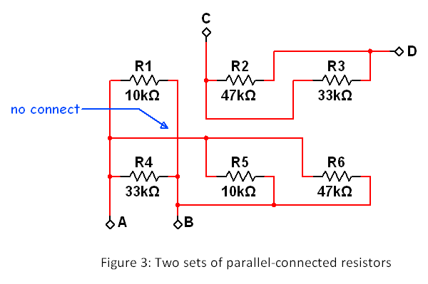
- Draw a sketch of your new breadboard layout.
- Calculate the equivalent resistance between terminals A and B using the nominal resistor values. Repeat this calculation using your measured resistance values.
- Calculate the equivalent resistance between terminals C and D using the nominal resistor values. Repeat this calculation using your measured resistance values.
- Measure and record the resistance between terminals A and B. Repeat for terminals C and D.
- Calculate the percentage difference between your measured values and your calculated values derived from the nominal resistor values.
- Calculate the percentage difference between your measured values and your calculated values derived from the measured resistor values.
D. Build your intuition:
- Respond: What is the typical level of agreement between your measured equivalent resistance (say, terminals A to B) and your calculated equivalent resistance based on nominal resistor values?
- Respond: What is the typical level of agreement between your measured equivalent resistance and your calculated equivalent resistance based on measured resistor values?
- Respond: Is it possible for the equivalent resistance of parallel-connected resistors to ever be higher than the smallest-valued resistor in the chain? Explain your answer.
- Respond: Suppose you have two equal-valued resistors with value R. What is the equivalent resistance of these two resistors connected in parallel?
- Respond: Suppose you have an arbitrary number (say N) of equal-valued resistors with value R. What is the equivalent resistance of these N resistors connected in parallel?
For more information
