- Subscribe to RSS Feed
- Mark Topic as New
- Mark Topic as Read
- Float this Topic for Current User
- Bookmark
- Subscribe
- Mute
- Printer Friendly Page
ADS1115 Labview Interface for Arduino
07-10-2015 05:14 AM
- Mark as New
- Bookmark
- Subscribe
- Mute
- Subscribe to RSS Feed
- Permalink
- Report to a Moderator
Hi,
I'm trying to configure a 16-bit ADC (ADS1115) using Labview Interface for Arduino and I2C communication. I have read the datasheet several times and I can't understand what is wrong.
Next figure shows the circuit. I have used the Arduino libraries from Adafruit and they worked properly. Both, single shot and differential read 26979 bits (5058,56 mV). So, the problem is not here, I think.
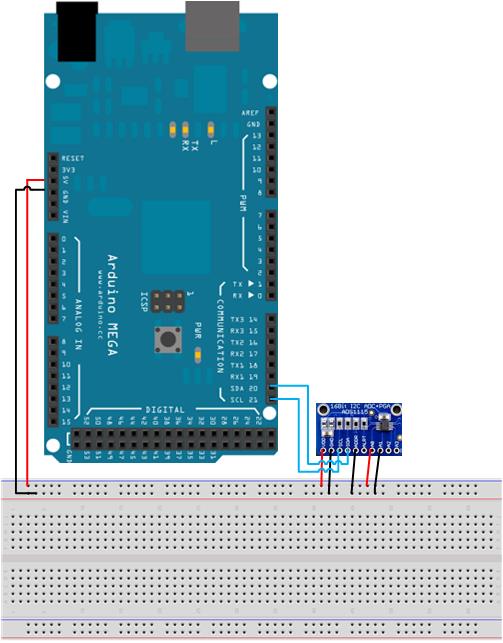
This ADC has a configurable gain (PGA). In the previous picture, in order to simplify all the connections, 5V are connected to A0 because in Arduino libraries, the default gain is 2/3 (range 6,144V). Next two examples the gain will be different (2x with range of 2,048V on the first one and 1x with range of 4,096V on the second one). Taking this into account, I have changed the input voltage of 5V to 1,6V for the first case and 3,3V for the second one. Once again, both of them worked perfectly using Arduino libraries, but not using Labview.
In datasheet, page 11, there is an example. These are the steps:
- Set the configuration register:
1st byte (Address + low R/W bit): 10010000 (144)
2nd byte (Pointer register): 00000001 (1)
3rd byte (Config. Reg. MSB): 10000100 (132)
4th byte (Config. Reg. LSB): 10000011 (131)
- Set the pointer register:
1st byte (Adress +low R/W bit): 10010000 (144)
2nd byte (Pointer Register to Conversion Reg.): 00000000 (0)
- Read the conversion register:
1st byte (Address + low R/W bit): 10010001 (145)
2nd byte (Conversion Reg. MSB response): read this byte
3rd byte (Conversion Reg. LSB response): read this byte
This is the .vi:
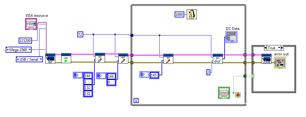
I should expect to make a continuous conversion and read the 1,6V, but I don't...
There is another example, quite similar. Here is the link: http://openlabtools.eng.cam.ac.uk/Resources/Datalog/RPi_ADS1115/
These are the steps:
- Set the configuration register:
1st byte (Address + low R/W bit): 10010000
2nd byte (Pointer register): 00000001 (1)
3rd byte (Config. Reg. MSB): 11000011 (195)
4th byte (Config. Reg. LSB): 00000011(3)
(The configuration is a little bit different. This is a single shot example)
- Read the configuration register:
1st byte (Address + low R/W bit): 10010001 (145)
2nd byte (Config. Reg. MSB response): read this byte
3rd byte (Config. Reg. LSB response): read this byte
(Read the config register, continuously loop this step until bit 15 of the config register is 1)
- Set the pointer register:
1st byte (Adress +low R/W bit): 10010000 (144)
2nd byte (Pointer Register to Conversion Reg.): 00000000 (0)
- Read the conversion register:
1st byte (Address + low R/W bit): 10010001 (145)
2nd byte (Conversion Reg. MSB response): read this byte
3rd byte (Conversion Reg. LSB response): read this byte
This is the .vi:
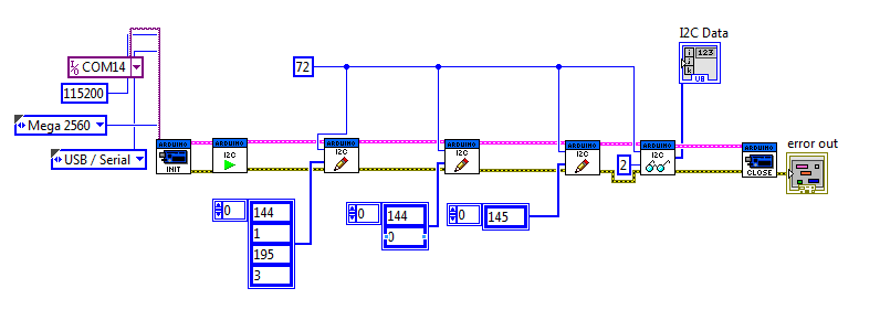
I should expect to make a single shot conversion and read the 3,3V, but I don't... Actually, it seems I'm reading the configuration register default values 10000101 10000011 (133 131).
I don't know where could be the problem. Any help will be appreciated.....!
Cheers,
Sergi
07-10-2015 10:56 PM
- Mark as New
- Bookmark
- Subscribe
- Mute
- Subscribe to RSS Feed
- Permalink
- Report to a Moderator
The mistake that you are making is that you are writing the device address twice. Once as the address and second as a data byte. The I2C device address is sent specially by the Arduino code so you should not include that as one of the data bytes.
Because of confusion like this, I tend to prefer trying to port the Arduino library for the device into LabVIEW if such a library exists (and isn't overly complicated).
You should also know that LIFA is old, outdated, and no longer officially supported. You should instead use LINX which is LIFA's replace, is much faster, and is actively supported and being developed to add more functionality. LabVIEW MakerHub is the official home of LINX. Also, given the code that you posted, LINX code will be nearly identical (Note that the "I2C Channel" will be 0 for all Arduinos).
P.S. LINX also includes support for many more micro controllers other than Arduino.
07-13-2015 04:37 AM
- Mark as New
- Bookmark
- Subscribe
- Mute
- Subscribe to RSS Feed
- Permalink
- Report to a Moderator
Hi, thank you for your replay. It has a lot of sense what you said. Also, thanks for your recommendations. I know a little bit about LINX, but I'm running a bit out of time and I don't know if it would be so easy to download, use, etc. I totally agree with you about using Arduino libraries, but the problem is I'm programming the whole software using Labview, I must use Labview. It's not just a code for Arduino.
I ran the code with only one address and it worked perfectly!! 
Thanks again for your help!
Sergi
07-13-2015 07:39 AM
- Mark as New
- Bookmark
- Subscribe
- Mute
- Subscribe to RSS Feed
- Permalink
- Report to a Moderator
http://www.transport-intelligent.net/technologies/systemes-cooperatifs/
2015-07-13 11:37 GMT+02:00 sergiclariana <web.community@ni.com>:
<https://decibel.ni.com/content/index.jspa> Re: ADS1115 Labview
Interface for Arduino created by sergiclariana
<https://decibel.ni.com/content/people/sergiclariana> in *LabVIEW
Interface for Arduino* - View the full discussion
<https://decibel.ni.com/content/message/106963#106963>
10-16-2017 03:46 AM
- Mark as New
- Bookmark
- Subscribe
- Mute
- Subscribe to RSS Feed
- Permalink
- Report to a Moderator
Hi Sergi,
I tried removing the address (144 and 145) in the data array, yet timeout occurred at the I2C Read.vi. I made sure the hardware is not the problem using Arduino example.
Could you share your revised example code?
10-31-2017 11:59 AM - edited 10-31-2017 11:59 AM
- Mark as New
- Bookmark
- Subscribe
- Mute
- Subscribe to RSS Feed
- Permalink
- Report to a Moderator
Hi,
i have the same problem that Linx + Arduino Uno + ADS1115 is not working.
Can anybody share a working code for labview?
I wired ADDR with GND and want to use the full range of 6V.
Thank you very much
11-06-2017 01:41 AM
- Mark as New
- Bookmark
- Subscribe
- Mute
- Subscribe to RSS Feed
- Permalink
- Report to a Moderator

Well, it works now, I just forgot to put the I2C Open.vi after the Open Serial.vi...
11-21-2017 07:29 PM
- Mark as New
- Bookmark
- Subscribe
- Mute
- Subscribe to RSS Feed
- Permalink
- Report to a Moderator
Dear, pichw. I'm working with the ADS1115 and your code but I don't understand the data that I get. Could you help me with the interpretation of the data please? Thanks.
pichw escribió:
Well, it works now, I just forgot to put the I2C Open.vi after the Open Serial.vi...
11-22-2017 02:18 AM
- Mark as New
- Bookmark
- Subscribe
- Mute
- Subscribe to RSS Feed
- Permalink
- Report to a Moderator
Firstly, there are 2 bytes you need to read, MSB and LSB. Secondly, the unit of the reading you get is related to the full scale you set. ADS1115 is a 16bits ADC, and 1 bit is used for sign, therefore when the full scale is +/-4.096V the unit of the reading is 4096/2^15 = 0.125 mV.

05-08-2018 09:01 PM
- Mark as New
- Bookmark
- Subscribe
- Mute
- Subscribe to RSS Feed
- Permalink
- Report to a Moderator
Dear All,
I am facing a problem with interfacing ADS1115 with LINX. I am able to communicate the ADS with INX but cannot figure out how to read exact analog data. I also want to read the differential voltage of A0-A1 and A2-A3 and want to change the PGA values. I am also concerned about the sign of the data like -2.5 mV. But I am getting some crazy data. How to configure the registers and write codes for the same. I am attaching the codes in VI. Please reply as soon as possible.
Thanks in advance...
