- Subscribe to RSS Feed
- Mark Topic as New
- Mark Topic as Read
- Float this Topic for Current User
- Bookmark
- Subscribe
- Mute
- Printer Friendly Page
Engine Simulation Toolkit Feedback
10-07-2014 03:33 PM
- Mark as New
- Bookmark
- Subscribe
- Mute
- Subscribe to RSS Feed
- Permalink
- Report to a Moderator
Hi Stephen,
I loaded the FPGA bitfile into engine simulation toolkit with correct input and output configuration, but it still generates 1V digital pattern. Is it set to be so? Or can I specify the amplitude through software?
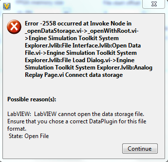
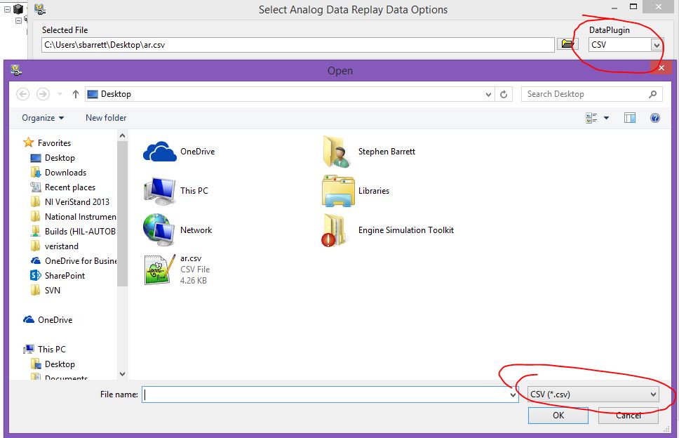
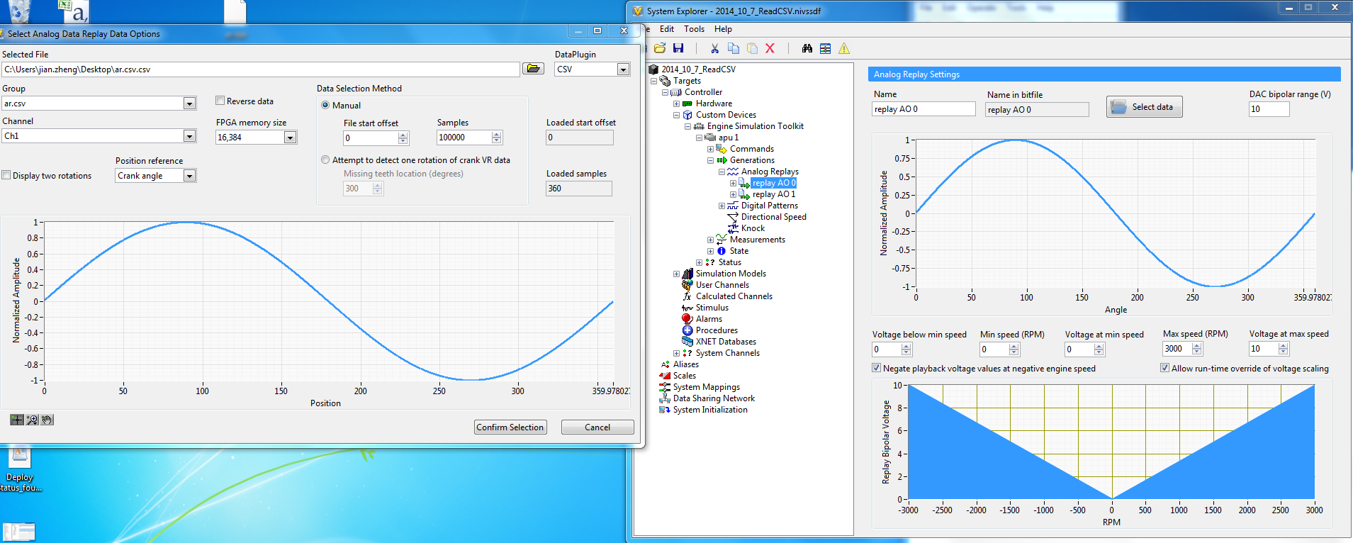
I am also trying to use the Analog Replay function, but the file explorer could not find the .csv or .dat file I have in the folder(DataPlugin section being specified as CSV or DAT). And if I make the file explorer show all files and select the csv or dat file, the following error will pop up. Are there specific requirements about the format? I have attached the csv and dat file I used.
Thanks.
Jian
10-07-2014 03:40 PM
- Mark as New
- Bookmark
- Subscribe
- Mute
- Subscribe to RSS Feed
- Permalink
- Report to a Moderator
Hi Jian,
The voltage generated by the digital pattern is dependent on the hardware you are using. As this is a support forum for the engine simulation toolkit only, I cannot assist in this regard. Please contact support for your hardware questions.
I was able to load the csv file. Make sure you select the CSV data plugin so that the file browser file filter changes to *.csv
10-07-2014 03:56 PM
- Mark as New
- Bookmark
- Subscribe
- Mute
- Subscribe to RSS Feed
- Permalink
- Report to a Moderator
Hi Stephen,
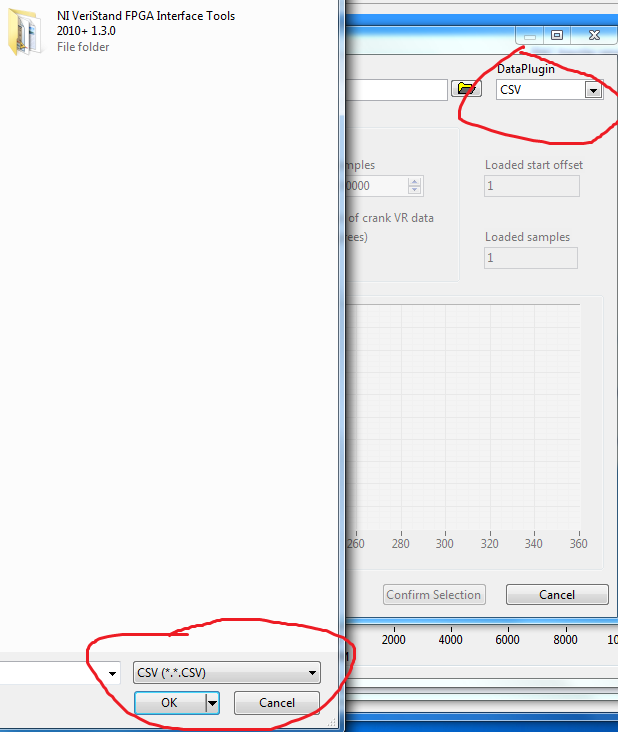
I think I found why, but I do not know how to fix it. My file filter shows as'*.*.CSV'.
And even if I load the example bitfile, it is still the same.
Jian
10-07-2014 03:59 PM
- Mark as New
- Bookmark
- Subscribe
- Mute
- Subscribe to RSS Feed
- Permalink
- Report to a Moderator
Oh wow strange. I dont see that on my machine or on another I just checked.
I will look into this further.
10-07-2014 05:02 PM
- Mark as New
- Bookmark
- Subscribe
- Mute
- Subscribe to RSS Feed
- Permalink
- Report to a Moderator
Hi Stephen,
Although that is a problem needs to be fixed, I think I might get away this problem by changing the data file name into xxx.csv.csv.
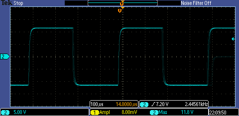
However, what I saw on oscilliscope is not sine wave but square waves whose amplitude is around 1V. I have imported a model into the Veristand project which outputs RPM. And I mapped this RPM to 'Desired Speed' in engine simulation toolkit. In my workspace, I can see the 'Actual Speed'(state of apu1) increases from 0 to around 2500. At the same time, the frequency of the generated squares waves increase to around 50Hz without any changes in amplitude.
Do you think that is the problem of the waveform data or other configurations not correctly set?
Thanks.
Jian
10-08-2014 09:28 AM
- Mark as New
- Bookmark
- Subscribe
- Mute
- Subscribe to RSS Feed
- Permalink
- Report to a Moderator
Hi Stephen,
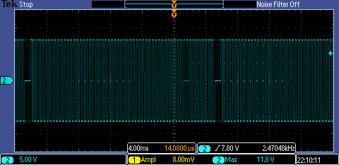
Can you try to generate the waveform using the attached tdms file? I still got digital-like signals rather than the waveform I specified in Analog Replay.
 as compared to
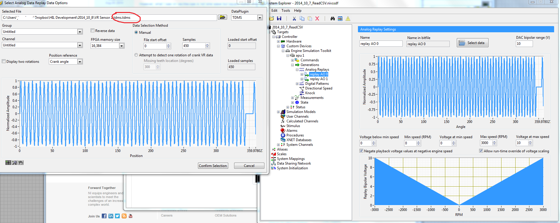
10-08-2014 12:31 PM
- Mark as New
- Bookmark
- Subscribe
- Mute
- Subscribe to RSS Feed
- Permalink
- Report to a Moderator
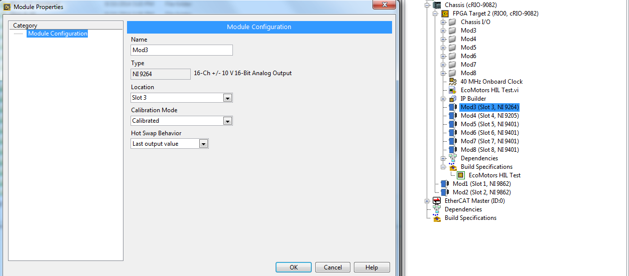
Hi JianZ,
The last screenshot you posted explains the problem. The module should be in uncalibrated / raw mode
10-08-2014 01:13 PM
- Mark as New
- Bookmark
- Subscribe
- Mute
- Subscribe to RSS Feed
- Permalink
- Report to a Moderator
Jian,
I have posted version 1.2.8 to resolve the *.*.csv issue you saw.
10-08-2014 02:26 PM
- Mark as New
- Bookmark
- Subscribe
- Mute
- Subscribe to RSS Feed
- Permalink
- Report to a Moderator
Thanks, Stephen
Raw mode does solve the problem.
Jian
10-13-2014 08:58 AM
- Mark as New
- Bookmark
- Subscribe
- Mute
- Subscribe to RSS Feed
- Permalink
- Report to a Moderator
Hi Stephen,
I am trying to calculate torque output based on the captured injection trigger by Event Timing Capture. It provides me the duration, start and end angle of trigger signal. I tried to use this information and compare the calculated crank angle from model (see if current crank angle is within the range of start&end angle) to determine real-time output torque. But I have to run the model at very high speed (3~5kHz) since in many cases the injection duration is around 1ms. I am wondering if this is how others do the torque calculation? Or do people modify the FPPA vi and integrate the torque calculation in FPGA rather than in model?
Thanks
Jian
