-
NI Community
- Welcome & Announcements
-
Discussion Forums
- Most Active Software Boards
- Most Active Hardware Boards
-
Additional NI Product Boards
- Academic Hardware Products (myDAQ, myRIO)
- Automotive and Embedded Networks
- DAQExpress
- DASYLab
- Digital Multimeters (DMMs) and Precision DC Sources
- Driver Development Kit (DDK)
- Dynamic Signal Acquisition
- FOUNDATION Fieldbus
- High-Speed Digitizers
- Industrial Communications
- IF-RIO
- LabVIEW Communications System Design Suite
- LabVIEW Electrical Power Toolkit
- LabVIEW Embedded
- LabVIEW for LEGO MINDSTORMS and LabVIEW for Education
- LabVIEW MathScript RT Module
- LabVIEW Web UI Builder and Data Dashboard
- MATRIXx
- Hobbyist Toolkit
- Measure
- NI Package Manager (NIPM)
- Phase Matrix Products
- RF Measurement Devices
- SignalExpress
- Signal Generators
- Switch Hardware and Software
- USRP Software Radio
- NI ELVIS
- VeriStand
- NI VideoMASTER and NI AudioMASTER
- VirtualBench
- Volume License Manager and Automated Software Installation
- VXI and VME
- Wireless Sensor Networks
- PAtools
- Special Interest Boards
- Community Documents
- Example Programs
-
User Groups
-
Local User Groups (LUGs)
- Denver - ALARM
- Bay Area LabVIEW User Group
- British Columbia LabVIEW User Group Community
- Chicago LabVIEW User Group
- Egypt NI Chapter
- GUNS
- Houston Area LabVIEW Community
- LabVIEW - University of Applied Sciences Esslingen
- [IDLE] LabVIEW User Group Stuttgart
- LUGG - LabVIEW User Group at Goddard
- LUGNuts: LabVIEW User Group for Connecticut
- Madison LabVIEW User Group Community
- Mass Compilers
- Melbourne LabVIEW User Group
- Midlands LabVIEW User Group
- Milwaukee LabVIEW Community
- Minneapolis LabVIEW User Group
- CSLUG - Central South LabVIEW User Group (UK)
- Nebraska LabVIEW User Community
- New Zealand LabVIEW Users Group
- NI UK and Ireland LabVIEW User Group
- NOCLUG
- Orange County LabVIEW Community
- Ottawa and Montréal LabVIEW User Community
- Washington Community Group
- Phoenix LabVIEW User Group (PLUG)
- Politechnika Warszawska
- PolŚl
- Rutherford Appleton Laboratory
- Sacramento Area LabVIEW User Group
- San Diego LabVIEW Users
- Sheffield LabVIEW User Group
- South East Michigan LabVIEW User Group
- Stockholm LabVIEW User Group (STHLUG)
- Southern Ontario LabVIEW User Group Community
- SoWLUG (UK)
- Space Coast Area LabVIEW User Group
- Sydney User Group
- Top of Utah LabVIEW User Group
- Utahns Using TestStand (UUT)
- UVLabVIEW
- Western NY LabVIEW User Group
- Western PA LabVIEW Users
- Orlando LabVIEW User Group
- Aberdeen LabVIEW User Group (Maryland)
- Gainesville LabVIEW User Group
- LabVIEW Team Indonesia
- Ireland LabVIEW User Group Community
- Louisville KY LabView User Group
- NWUKLUG
- LVUG Hamburg
- LabVIEW User Group Munich
- LUGE - Rhône-Alpes et plus loin
- London LabVIEW User Group
- VeriStand: Romania Team
- DutLUG - Dutch LabVIEW Usergroup
- WaFL - Salt Lake City Utah USA
- Highland Rim LabVIEW User Group
- NOBLUG - North Of Britain LabVIEW User Group
- North Oakland County LabVIEW User Group
- Oregon LabVIEW User Group
- WUELUG - Würzburg LabVIEW User Group (DE)
- LabVIEW User Group Euregio
- Silesian LabVIEW User Group (PL)
- Indian LabVIEW Users Group (IndLUG)
- West Sweden LabVIEW User Group
- Advanced LabVIEW User Group Denmark
- Automated T&M User Group Denmark
- UKTAG – UK Test Automation Group
- Budapest LabVIEW User Group (BudLUG)
- South Sweden LabVIEW User Group
- GLA Summit - For all LabVIEW and TestStand Enthusiasts!
- Bangalore LUG (BlrLUG)
- Chennai LUG (CHNLUG)
- Hyderabad LUG (HydLUG)
- LUG of Kolkata & East India (EastLUG)
- Delhi NCR (NCRLUG)
- Montreal/Quebec LabVIEW User Group Community - QLUG
- Zero Mile LUG of Nagpur (ZMLUG)
- LabVIEW LATAM
- LabVIEW User Group Berlin
- WPAFB NI User Group
- Rhein-Main Local User Group (RMLUG)
- Huntsville Alabama LabVIEW User Group
- LabVIEW Vietnam
- [IDLE] ALVIN
- [IDLE] Barcelona LabVIEW Academic User Group
- [IDLE] The Boston LabVIEW User Group Community
- [IDLE] Brazil User Group
- [IDLE] Calgary LabVIEW User Group Community
- [IDLE] CLUG : Cambridge LabVIEW User Group (UK)
- [IDLE] CLUG - Charlotte LabVIEW User Group
- [IDLE] Central Texas LabVIEW User Community
- [IDLE] Cowtown G Slingers - Fort Worth LabVIEW User Group
- [IDLE] Dallas User Group Community
- [IDLE] Grupo de Usuarios LabVIEW - Chile
- [IDLE] Indianapolis User Group
- [IDLE] Israel LabVIEW User Group
- [IDLE] LA LabVIEW User Group
- [IDLE] LabVIEW User Group Kaernten
- [IDLE] LabVIEW User Group Steiermark
- [IDLE] தமிழினி
- Academic & University Groups
-
Special Interest Groups
- Actor Framework
- Biomedical User Group
- Certified LabVIEW Architects (CLAs)
- DIY LabVIEW Crew
- LabVIEW APIs
- LabVIEW Champions
- LabVIEW Development Best Practices
- LabVIEW Web Development
- NI Labs
- NI Linux Real-Time
- NI Tools Network Developer Center
- UI Interest Group
- VI Analyzer Enthusiasts
- [Archive] Multisim Custom Simulation Analyses and Instruments
- [Archive] NI Circuit Design Community
- [Archive] NI VeriStand Add-Ons
- [Archive] Reference Design Portal
- [Archive] Volume License Agreement Community
- 3D Vision
- Continuous Integration
- G#
- GDS(Goop Development Suite)
- GPU Computing
- Hardware Developers Community - NI sbRIO & SOM
- JKI State Machine Objects
- LabVIEW Architects Forum
- LabVIEW Channel Wires
- LabVIEW Cloud Toolkits
- Linux Users
- Unit Testing Group
- Distributed Control & Automation Framework (DCAF)
- User Group Resource Center
- User Group Advisory Council
- LabVIEW FPGA Developer Center
- AR Drone Toolkit for LabVIEW - LVH
- Driver Development Kit (DDK) Programmers
- Hidden Gems in vi.lib
- myRIO Balancing Robot
- ROS for LabVIEW(TM) Software
- LabVIEW Project Providers
- Power Electronics Development Center
- LabVIEW Digest Programming Challenges
- Python and NI
- LabVIEW Automotive Ethernet
- NI Web Technology Lead User Group
- QControl Enthusiasts
- Lab Software
- User Group Lead Network
- CMC Driver Framework
- JDP Science Tools
- LabVIEW in Finance
- Nonlinear Fitting
- Git User Group
- Test System Security
- Product Groups
-
Partner Groups
- DQMH Consortium Toolkits
- DATA AHEAD toolkit support
- GCentral
- SAPHIR - Toolkits
- Advanced Plotting Toolkit
- Sound and Vibration
- Next Steps - LabVIEW RIO Evaluation Kit
- Neosoft Technologies
- Coherent Solutions Optical Modules
- BLT for LabVIEW (Build, License, Track)
- Test Systems Strategies Inc (TSSI)
- NSWC Crane LabVIEW User Group
- NAVSEA Test & Measurement User Group
-
Local User Groups (LUGs)
-
Idea Exchange
- Data Acquisition Idea Exchange
- DIAdem Idea Exchange
- LabVIEW Idea Exchange
- LabVIEW FPGA Idea Exchange
- LabVIEW Real-Time Idea Exchange
- LabWindows/CVI Idea Exchange
- Multisim and Ultiboard Idea Exchange
- NI Measurement Studio Idea Exchange
- NI Package Management Idea Exchange
- NI TestStand Idea Exchange
- PXI and Instrumentation Idea Exchange
- Vision Idea Exchange
- Additional NI Software Idea Exchange
- Blogs
-
Events & Competitions
- FIRST
- GLA Summit - For all LabVIEW and TestStand Enthusiasts!
- Events & Presentations Archive
- Optimal+
-
Regional Communities
- NI中文技术论坛
- NI台灣 技術論壇
- 한국 커뮤니티
- ディスカッションフォーラム(日本語)
- Le forum francophone
- La Comunidad en Español
- La Comunità Italiana
- Türkçe Forum
- Comunidade em Português (BR)
- Deutschsprachige Community
- المنتدى العربي
- NI Partner Hub
-
 lizhuo_lin
on:
Stereo vision (OpenCV and Labview comparison)
lizhuo_lin
on:
Stereo vision (OpenCV and Labview comparison)
-
 张斌
on:
Point cloud registration tool
张斌
on:
Point cloud registration tool
-
 GohanTYO
on:
Qt+PCL+OpenCV (Kinect 3D face tracking)
GohanTYO
on:
Qt+PCL+OpenCV (Kinect 3D face tracking)
-
 Klemen
on:
Qt GUI for PCL (OpenNI) Kinect stream
Klemen
on:
Qt GUI for PCL (OpenNI) Kinect stream
-
efreet
on:
OpenCV and Qt based GUI (Hough circle detection example)
-
Spalabuser
on:
Homography mapping calculation (Labview code)
-
rameshr
on:
Optical water level measurements with automatic water refill in Labview
-
xuexue0224
on:
Kalman filter (OpenCV) and MeanShift (Labview) tracking
-
Aaatif
on:
Serial data send with CRC (cyclic redundancy check) - Labview and Arduino/ARM
-
hsaid
on:
Color image segmentation based on K-means clustering using LabVIEW Machine Learning Toolkit
Mini laser scanner - part 3 (scanning)
- Subscribe to RSS Feed
- Mark as New
- Mark as Read
- Bookmark
- Subscribe
- Printer Friendly Page
- Report to a Moderator
I have managed to get my laser scanning system working. I still have some problems since there are some perspective errors (distortions) in my scans, which I still need to correct.
Figure 1 shows the scanning setup. The frame is from thin sheet metal (2 mm), which was bent by hand with the help of a vice. The camera and the laser projector are attached to this frame using a seperate thin sheet metal frame. The geometry was designed according to the calculations I have made in the previous post (Mini laser scanner - part 2). All the components were fastened to a wooden board. I also used a thick white cardboard as a pedestal to reflect the laser light more efficiently.
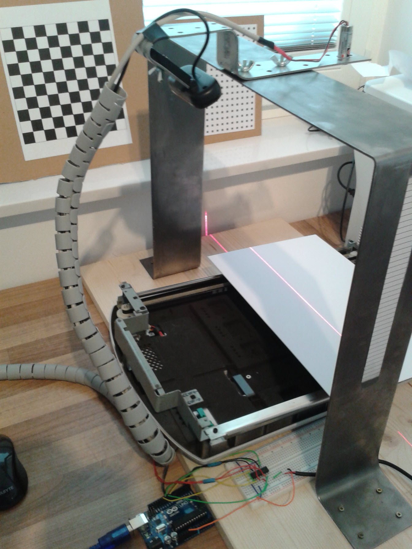
Figure 1. Laser scanning system setup.
To successfully calculate the points in 3D space, some parameters have to be determined:
1. Intrinsic camera parameters (fu, fv, cu, cv, k1, k2, p1, p2). These were determined using a chessboard pattern and camera calibration toolbox in Matlab. For comparison, I also determined the same parameters using the NI calibration training interface and a dot pattern grid.
2. Extrinsic camera-projector parameters (Py, Pz, alpha). Py and Pz are the coordinates of the laser projector in the camera coordinate system. Alpha is the triangulation angle. These parameters were not accurately determined, since there is some math behind this. I would also need a reference body with known dimensions and iterative algorithms (which I do not have, nor do I have the time to code them) to determine the smallest deviation between the measured and the reference surface. Currently I do not know of any other methods to determine the mentioned parameters. If anyone knows alternative methods, please share them…
So instead I attached a measuring tape to the frame (can be seen in the Figure 1) and photographed the measuring system from the side, so that the optical axis of the camera and the laser were parallel (or close to parallel) to the image plane (photographed). The image was transferred to Autocad and the required parameters measured and transformed to real-world units using the measuring tape of known spacing.
3. Transformation parameters from camera to world coordinate system. In order to take into account the motion of the stepper motor, the 3D camera coordinates have to be transformed to the world coordinate system (stepper motor coordinate system). Thus, the speed of the motor in the motion direction can be taken into account and the subsequent acquired profiles can be spaced accordingly. The transformation from camera coordinate system to world coordinate system was also performed using the Matlab camera calibration toolbox.
The speed of the motor in real-world units (at different steps and speeds) was determined by measuring the traveled distance (laser line as the reference) in the corresponding time (Arduino timer library). For all the presented scans, my scan speed was ~2.1 mm/s.
Video 1 shows an example of a scan and here is the link to youtube video: http://www.youtube.com/watch?v=Krd4lKoVa8k
Video 1. Example of a scanned hand.
Figure 2 shows another scan of an object (small radio with speaker).
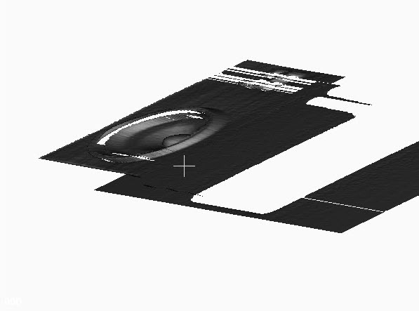
Figure 2. Scanned radio speaker.
Figure 3. shows another scan of a refrigerator magnet.
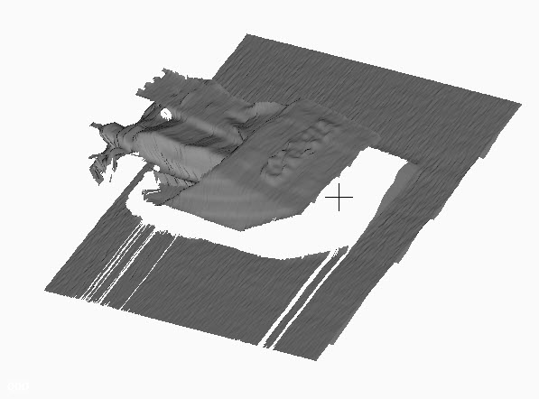
Figure 3. Scanned refrigerator magnet.
The laser scanning system is not perfect, but it server the main purpose – learning something new every day.  I think it would be better to move the camera-projector pair and not the pedestal where the object is placed. But this is another story for another day. To put it plainly – my scanning system needs a lot of improvement in order to get accurate scans. But the main principle of laser scanning is covered in my mini scanner project. Maybe I will take some time in the future to improve it.
So, the total cost of the system:
1. camera: 20 eur,
2. projector: 4.6 eur,
3. filter: 3.5 eur,
4. motor driver: 1.9 eur,
5. old document scanner with stepper motor: free
6. frame (with screws, nuts, etc…): 10 eur,
7. wooden board and cardboard pedestal: 5 eur.
Total costs: 45 eur.
Not counting the Arduino which I use for other stuff and was already here before the scanning system.
So the total cost is half the cost I predicted at the beginning. Yippee!
Thanks for reading.
Be creative.
https://decibel.ni.com/content/blogs/kl3m3n
"Kudos: Users may give one another Kudos on the forums for posts that they found particularly helpful or insightful."
You must be a registered user to add a comment. If you've already registered, sign in. Otherwise, register and sign in.
