Synchronize Encoder Counter Input and Analog Input with DAQmx
- Subscribe to RSS Feed
- Mark as New
- Mark as Read
- Bookmark
- Subscribe
- Printer Friendly Page
- Report to a Moderator
Products and Environment
This section reflects the products and operating system used to create the example.To download NI software, including the products shown below, visit ni.com/downloads.
- Data Acquisition (DAQ)
Hardware
- LabVIEW
Software
- NI DAQmx
Driver
Code and Documents
Attachment
Overview
Synchronize a Counter (Angular Encoder) task with an Analog Input task.
Description
This VI will take data at the same rate from both a counter input task, set up here to be an angular encoder, and an analog input task. The Analog Input sample clock is used as the sample clock for both tasks, such that they will both acquire data at the same rate. This VI will also take the counter output and place it into a waveform with the same timing information as the analog data. This allows all the data to be plotted on the same graph.
*Note: The "Get Terminal Name With Device Prefix.vi" subVI automatically selects generates the full terminal name (such as Dev1/ai/sampleclock) and routes it to the sample clock source for the counter. If this subVI does not load, you can easily create a control for the counter's sample clock source and select DevX/ai/sampleclock where DevX is the device name of your DAQ card. The "Get Terminal Name With Device Prefix" VI simply does that behind the scenes rather than needing a user to select it
Requirements to Run
Software
- LabVIEW 8.6 or compatible
- DAQmx 8.7.2 or compatible
Hardware
- Any NI analog DAQ device with a counter
Steps to Implement or Execute Code
- Open "Get Terminal Name with Device Prefix.vi"
- Open "Meas Angular Position-Buffered-Cont-Sync AI Sample Clk.vi"
- Set parameters in the front panel of "Meas Angular... .vi"
- Encoder Channel Parameters: configure the desired physical counter, decoding type, Z index value and Phase (if enabled), Pulses per Revolution, and Units
- Analog Channel Parameters: configure the desired Physical Channel, Minimum Value and Maximum Value
- Timing Parameters: set the Sampling Rate (Hz) and Samples to Read
- Run VI
- Note that details on the code execution are listed in the block diagram.
Additional Information or References
Block Diagram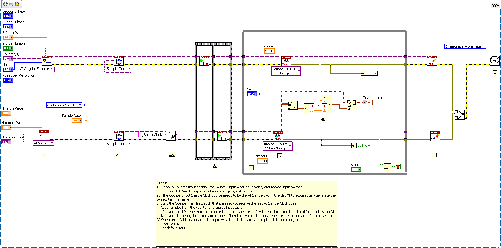
**This document has been updated to meet the current required format for the NI Code Exchange.**
AE Specialist | Global Support
National Instruments
Example code from the Example Code Exchange in the NI Community is licensed with the MIT license.
- Mark as Read
- Mark as New
- Bookmark
- Permalink
- Report to a Moderator
Does anyone know if this works with a CI Freq input instead of a encoder? I've attempted to use it for that purpose but I'm frequently getting a "Multiple sample clock pulses were detected within one period of the input signal" error. I'm guessing it stems from the input signal not being fast enough (it's a tach with just one pulse per revolution).
- Mark as Read
- Mark as New
- Bookmark
- Permalink
- Report to a Moderator
In This configuration, is there any way to measure speed (angular velocity) from the position data and synchronize it with voltage measurement? I mean measure angular velocity form the position while defining sampling rate & samples per loop?
