- Document History
- Subscribe to RSS Feed
- Mark as New
- Mark as Read
- Bookmark
- Subscribe
- Printer Friendly Page
- Report to a Moderator
- Subscribe to RSS Feed
- Mark as New
- Mark as Read
- Bookmark
- Subscribe
- Printer Friendly Page
- Report to a Moderator
Contact Information
University and Department: Instituto Tecnológico y de Estudios Superiores de Monterrey, Mexico City Campus, División de Ingeniería y Arquitectura
Team Members: Mauro Aja Prado, Roberto Guerrero Zurita
Faculty Advisors: Dr. Pedro Ponce Cruz
Primary Email Address: pedro.ponce@itesm.mx
Primary Telephone Number (include area and country code):+52 55 5483-2185
Project Information
Project Title: Modeling of human eye using artificial intelligence
List all parts (hardware, software, etc.) you used to design and complete your project:
· Labview 8.5
· Matlab
· NI USB-6008
· Dynalloy Flexinol Electrostem Air Valve
· Air Compressor
· Homemade air muscles
· Air distributor
· Plastic hoses
· Electrodes
· Computer power supply
Describe the challenge your project is trying to solve.
To design a model for describing the human eye’s movement which allows a clear understanding of the joint action of the muscles involved in ocular movement with didactic purposes in areas such as medicine and ophthalmology. The relationship between the muscles for positioning the eye in a new target is not an easy task with strong nonlinear relationships. The AI program has to control the movements of the eye’s physical prototype via manual position or using Electrooculography (EOG).
Describe how you addressed the challenge through your project.
Program
For the making of these project two artificial intelligence techniques where used, an Adaptive Network-Based Fuzzy Inference System (ANFIS) and Hebbian Artificial Neural Networks. An ANFIS is a system that uses neural networks and fuzzy logic to create an expert system. With the use of this expert system we can obtain the position of each muscle for each movement of the eye. Its main advantage is vector analysis. The Hebbian neural networks are implemented as a signal classifier to recognize the signals produced from the EOG. An advantage of this technique is that the connections of the artificial neurons can be processed in parallel, converging fast to a result. The network can be trained to function with any user.
The system used for the main GUI is an ANFIS with two inputs and one output. The inputs are coordinates in the X and Y axes in which the eye moves. Three triangular membership functions where used for each axis. To train the system we researched the percentage of elongation of each muscle for each movement. From these facts we chose to normalize the minimum value that represents the maximum contraction and maximum values to represent the maximum elongation of each muscle fixing the biggest value as the unity value. The ANFIS network was created with the use of Labview and Matlab. In the ANFIS network the number and form of the membership functions was fixed to three triangular functions. The learning algorithm used was backpropagation with a maximum of 5% error allowed. The results throw 9 rules with equal number of output functions of Singleton type where finally using the mass center equation we obtained a crisp output value. The system was programmed in National Instruments LabView software due to its easy connection to acquisition cards and its graphical programming language.
An electrooculography module was implemented to have another option of controlling the model. In this module the signals from the acquisition card are processed depending on the characteristic of the signal. Each signal produced by the movement of the eye has its own shape. In the EOG module graphical interface, two graphs are used to show the input signals from the acquisition card for the up/down/blink channel and for the left/right channel. Two plots show the signal after being filtered with a lowpass filter to reduce noise on the signal. A third plot shows the recognized signal. To train the ANN to recognize the signal first we have to train the system by clicking the Main train button which will turn it on. To train the system to recognize the blink signal first click the radial button to filter the signals except for the blink signal. If the signal is recognized, in the recognized signal graph a red signal will appear for about a second. In that time the user has to click on the Train blink button and click it again once the red graph disappears. On the Error blink text a number will appear. For the movements up, down, left, and right the process of training is the same as described above. To finish the training you have to train all of the movements and finally click on the Main train button again.
The main graphical interface with EOG, shows a switch with which you decide where to get the signal from, the EOG or manual using the knobs. It also shows six LEDs that turn on depending on the position it receives from the EOG.
Physical Prototype
For making the physic model of the eye, a model of the right eye with a 5:1 scale was built using really simple materials. The eye was built using a white acrylic sphere of 120 millimeters diameter and the iris was drawn using water based paints. For making the frame in which the eye was located a transparent resin box simulating the eye cavity was used. The system that held and allowed the rotational movement of the eye consist of 4 rolling devices “roll on” which were fixed to the base and in contact to the eye at all time. The muscles were attached to the acrylic sphere using small screws. All the muscles were positioned with the same origin with the exception of the obliques.
Homemade air muscles based on termofit and lycra fabric were used as the actuators. When these muscles are filled with air they expand and when they get empty they contract, they are really light and generate enough force for the desired requirements. Six muscles were used. To create the muscles a screw is inserted in one extreme of the termofit and a heat source is applied; the termofit shrinks and adheres to the screw sealing that side. In the other extreme of the termofit the plastic hose is placed and the same procedure has to be followed. Then a piece of the lycra fabric has to be used to cover the termofit, the lycra has to be approximately ¾ of the length. The lycra fabric gets held using the plastic fasteners by the top extreme, then it gets stretched and held by the other side. Because the length of the lycra fabric is less, the muscle will deform. Once an air inlet is applied on it, the muscle will stretch to its full length, then when the air stops flowing the muscle will get back to its original shape
In order to move the muscles we used proportional air valves from Dynalloy which are based on Flexinol. These valves can very gradually open or close the stem caps to produce proportionally controlled air flow. While heated with internal resistance the Flexinol contracts and open the cap; however, as it opens air begins to flow through and cool the same wire. The equilibrium between the electrical input and the mass of air entering the valve determines the aperture size and air flow. Electrostem valves are based primarily on a thermal reaction generated by the supplied current. According to the data sheet the valves can handle up to 2 Amperes at 100 psi, which was perfect for our requirements. For the implementation we used 3 National Instruments Acquisition Cards NI USB-6008.
Because we are limited by the fact that we have only 2 analog outputs per card and that we need to use one per muscle, we have to use 3 of these cards at the same time in order to move all 6 muscles. Another restrain is that as mentioned above the electrostem valves are controlled by current when these cards are supplying analog outputs of ± 10 volts with at most 5 milliamperes of current.
According to the software and for simplicity of design we chose to use the control signal for the muscles from 0 to 5 volts in order to produce from 0 to 1 ampere which assured a proper functioning of the valves. For doing this we created proportional conversion modules. Each module has a voltage to current convertor with load to ground plus a power stage using transistors TIP 41 and TIP 42 for amplifying the current in a push-pull array, an op amp for compensation of the 0.7 volts drop of the emitter followers and another op amp for impedance coupling and protection of the acquisition cards.
As mentioned before, the eye movement is either controlled by the software or by EOG, so a specific circuit was designed for this purpose. In the circuit the signals are acquired by electrodes connected to detect the eye movements. The circuit can only detect two signals either vertical or horizontal, therefore to achieve the 4 basic positions the circuit was repeated in the same board.
EOG is based on registering the resting potential of the retina, in other words is the potential difference that exists between the cornea and the retina. This potential is generated by hyperpolarizations and depolarizations. While using these potential differences it is possible to acquire the vertical and horizontal movements of the eye and to recognize the blinking.
If the eye is moved from the primary position towards one electrode, this electrode gets the positive side of the retina and the opposite electrode gets the negative side. In order to acquire the signals five electrodes are used. Two electrodes are for detecting the vertical movements, two to detect the horizontal movements and one used as the reference. The obtained signals are of about 20 mvolts and 6 Hz.
Representing accurately the human eye movement using vector or mechanical analysis results very complicated because of the complexity of the human vision system. Nevertheless, turns out to be easier to understand how is the eye movement produced with the use of everyday language as “too much” or “too little”. With use of artificial intelligence techniques such movements can be represented rather than a complex process to a simple and easy to understand process, achieving a good approximation of the real movement without the use of an expert to explain. Artificial intelligence techniques can be used as the link between physiology and engineering. With the use of this system medicine students can comprehend in a more interactive and didactic way such complexities.
The muscles were very difficult to reproduce since the real muscles can be contracted and elongated. The design of the air muscles can elongate easily; but the contraction was made by rubber bands which not always apply the same force.
Through the characterization of signals produced by the human body we can process them in a way computers can understand, making it easier to analyze and reproduce. The idea of this project can also be generalized to any other part of the body with its respective limitations, due to its complexity.
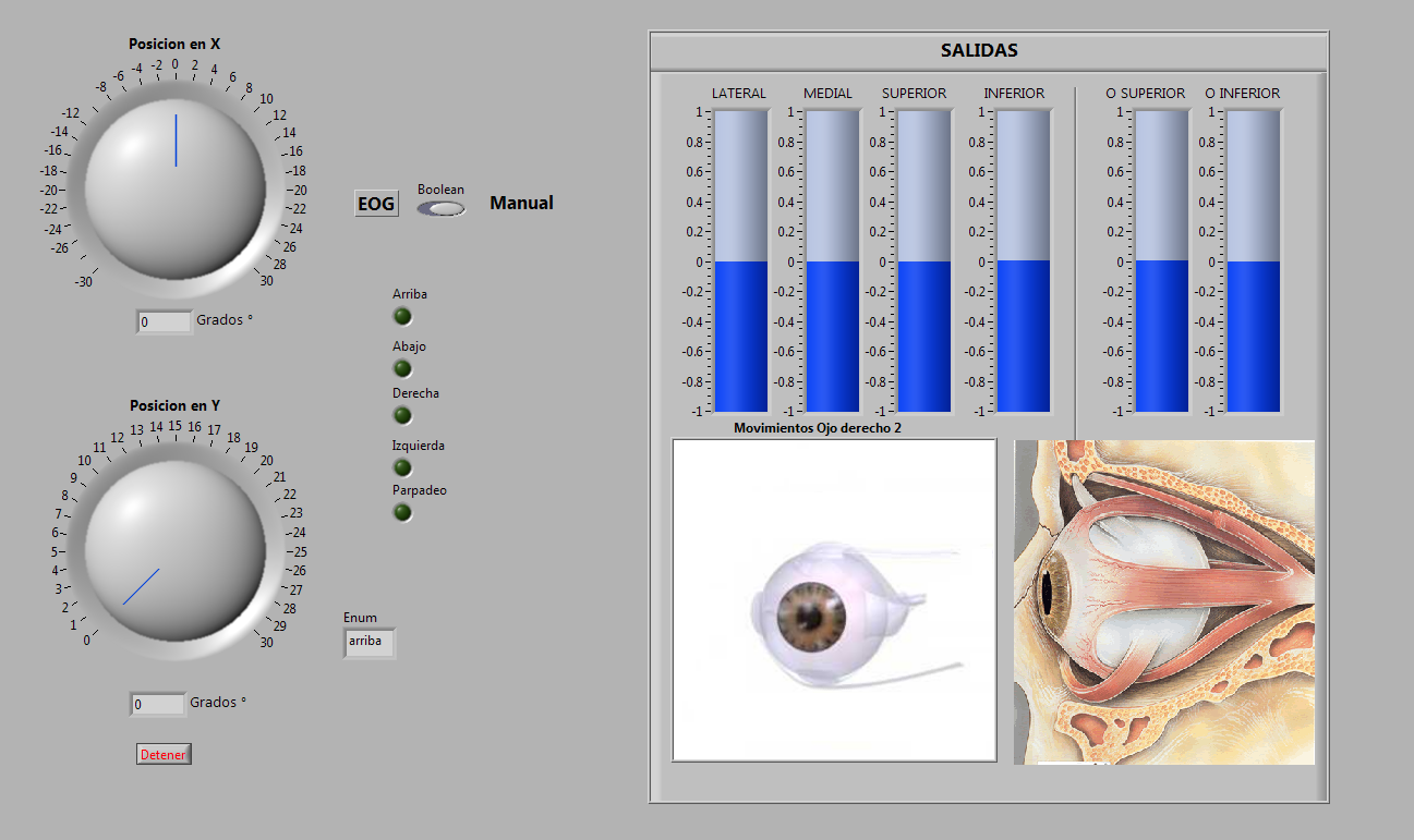
Figure 1 Graphic interface with EOG
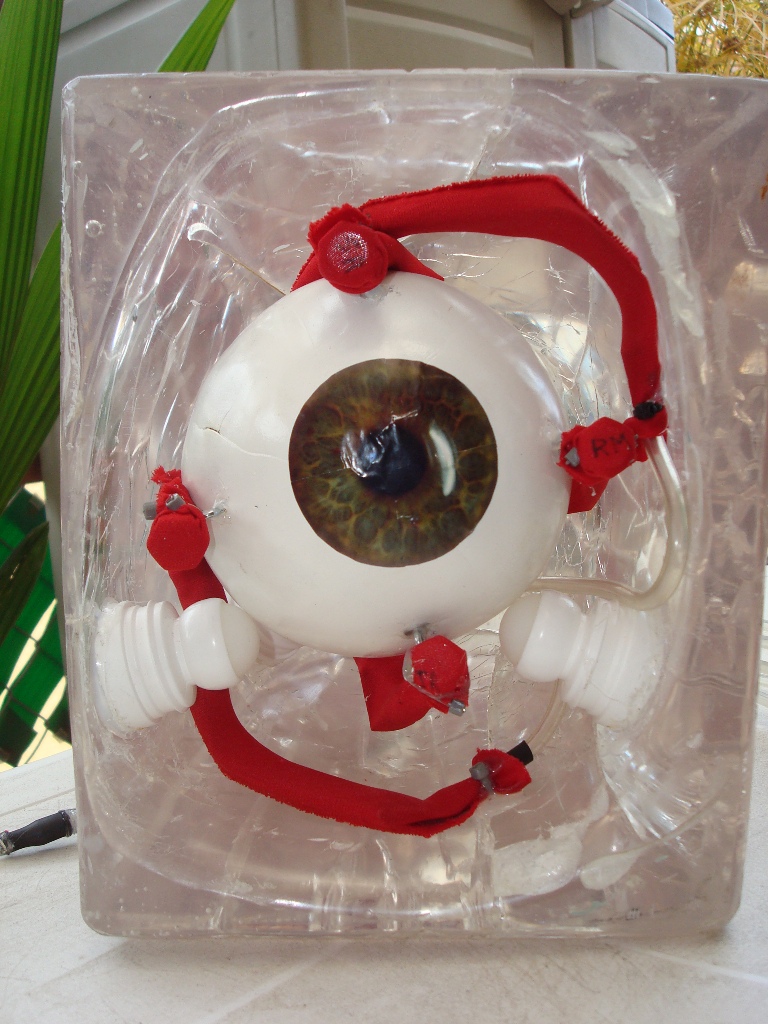
Figure 2 Physical prototype front view
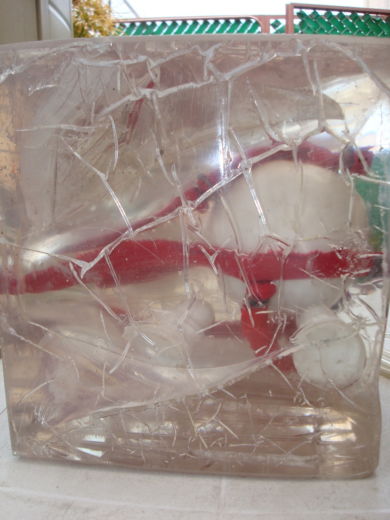
Figure 3 Physical prototype side view
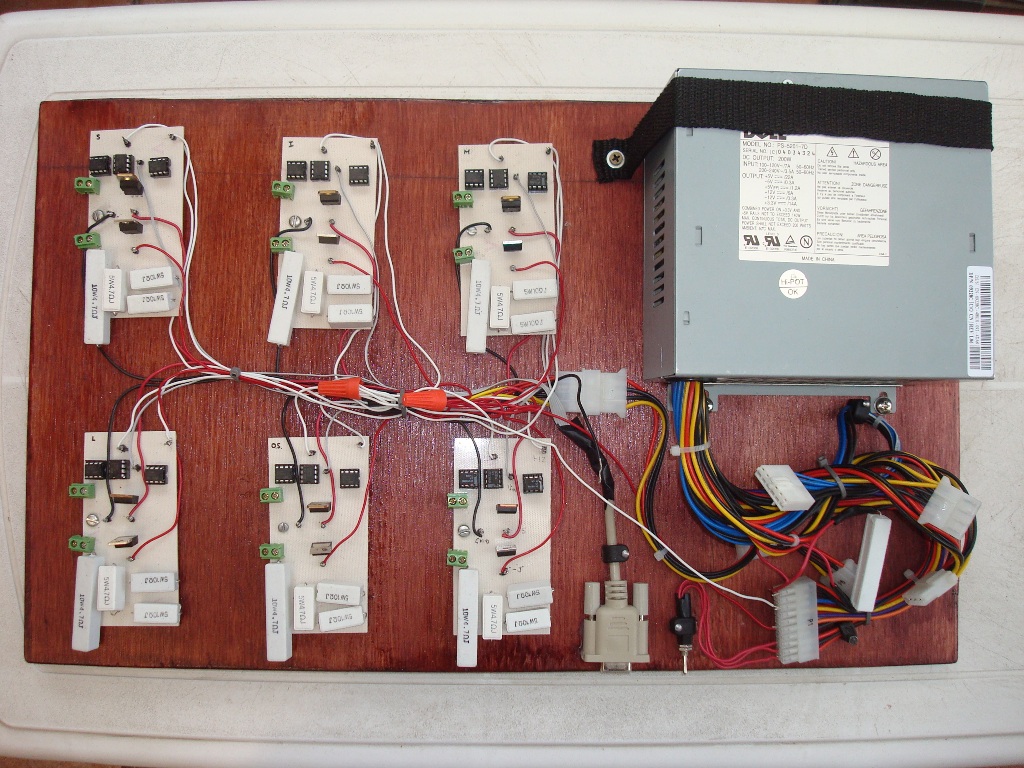
Figure 4 Set of proportional conversion modules with power supply
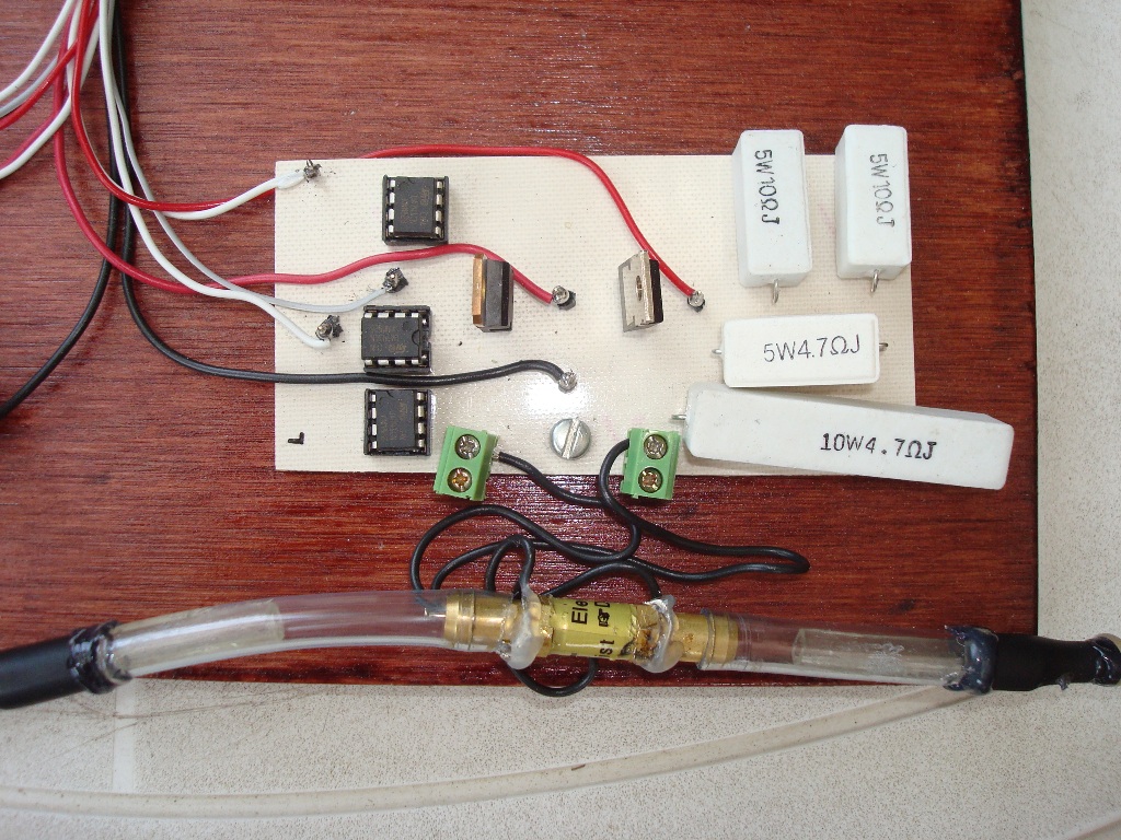
Figure 5 Single module and proportional valve
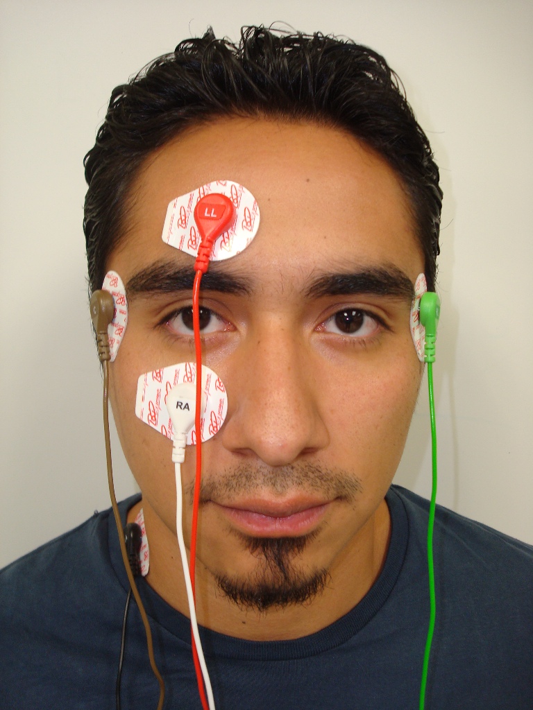
Figure 6 Position of electrodes for EOG
- Mark as Read
- Mark as New
- Bookmark
- Permalink
- Report to a Moderator
This is an awesome application! Thank you for submitting. What was the most challenging component of your project, Modeling of human eye using artificial intelligence?
- Mark as Read
- Mark as New
- Bookmark
- Permalink
- Report to a Moderator
Thank you for your comment. Well I think the hardest part was the integration of all the systems. Also the physical prototype presented many challenges, especially the air muscles.
