From Friday, April 19th (11:00 PM CDT) through Saturday, April 20th (2:00 PM CDT), 2024, ni.com will undergo system upgrades that may result in temporary service interruption.
We appreciate your patience as we improve our online experience.
From Friday, April 19th (11:00 PM CDT) through Saturday, April 20th (2:00 PM CDT), 2024, ni.com will undergo system upgrades that may result in temporary service interruption.
We appreciate your patience as we improve our online experience.
Contact Information
University and Department: University of Colorado at Boulder - Aerospace Engineering
Team Members: Dan Ambrosio, Ryan Del Gizzi, Bobby Hodgkinson, Jared Kirkpatrick, Colin Miller, Julie Price, Tyler Thomas
Faculty Advisors: Professor Kamran Mohseni
Primary Email Address: daniel.ambrosio@colorado.edu
Primary Telephone Number (include area and country code): (303) 921-6204
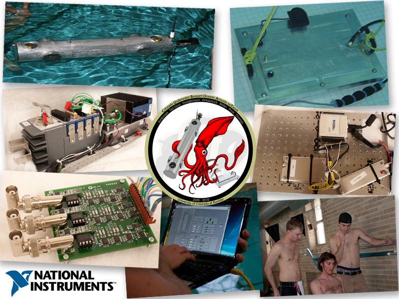
Project Title: Colorado Underwater Buoyant Oceanic Acoustic neTwork (CUBOAT)
![]()
List all parts (hardware, software, etc.) you used to design and complete your project:
Vehicle Hardware: NI cRIO-9014, NI cVision (To Be Implemented), NI 9264 Analog Output Module, NI 9401 High Speed Digital Output Module, NI 9205 Analog Input Module, NI 9403 Digital Output Module, Analog Devices IMU, OceanServer Digital Compass, 3 Seabotix HPDC1500 Brush-Less DC thrusters, 4 Inhouse Designed Vortex Ring thrusters (VRTs) w/ Faulhaber 3257 Coreless Motors, Linkskey Ethernet Switch, 2 Pololu TReX Jr Motor Controllers, 4 Advanced Motion Controls AZBE6A8 motor controllers, WetMate Ethernet Connector, Honeywell Pressure Sensor, 3 Reson Hydrophones, SQ26 Hydrophone, 3 MTI Ltd Pre-Amplifiers, In-house Power Distribution, Localization, Communication and other Electronic Boards.
Vehicle Software: NI LabVIEW 9
Command Module Hardware: Acer AS 1410 Laptop, NI USB 6501 DAQ, WetMate Ethernet Connector, Power Distribution Board, In-house Communication Board, RJE Underwater Pinger.
Command Module Software: Windows 7, LabVIEW 9
Other Design Software: MATLAB (Simulation), Solidworks 2009, Altium
Describe the challenge your project is trying to solve.
The objective of the CUBOAT project is to develop and demonstrate an acoustic network system capable of relaying and executing mission plans from an operator to an autonomous underwater vehicle (AUV) via underwater transmission. The acoustic network system is broken down into three main components: vehicle localization, vehicle control and data communication between underwater nodes (AUV, command module, etc.). Current commercial localization and data communication hardware components are either overly large or overly expensive. The acoustic communication system used by the CUBOAT project was designed to be inexpensive and compact allowing for easy integration and minimal modifications of existing underwater vehicles.The acoustic network system utilizes two different underwater nodes, the KRAKEN bio-inspired AUV (developed at the University of Colorado at Boulder) and an underwater Command Module.
The Command Module (located at the bottom of the testing environment) can send location, rotation, depth and many other data packets to the vehicle using the developed underwater communication system. Once the vehicle receives and "unpacks" the data control algorithms (located on the cRIO FPGA) maneuver the vehicle to complete the desired data packet information. The control algorithms utilize the vehicles onboard sensors, thrusters, and localization hardware/software to determine the states of the vehicle during the entire mission.
Future work entails competing in the AUVSI AUV collegiate competition, further progressing underwater communication protocols on efficient, inexpensive AUV systems, and cooperative control between multiple bio-inspired AUVs.
Describe how you addressed the challenge through your project.
The KRAKEN AUV was designed and built by a senior project group in Kamran Mohseni's Mobile Sensor Networking Platforms Laboratory in 2007-2008. The vehicle incorporates Vortex Ring Thrusters (VRTs), which are bio-inspired thrusters previously designed by Professor Mohseni and his graduate students at the University of Colorado at Boulder. The VRTs, which mimic the propulsive mechanism of squids, can propel the vehicle laterally and allow it to execute zero-radius yaw rotation while maintaining a low external profile with minimal drag. While many competitors use box-shaped designs as a result of their inherit advantages in low speed maneuvering, these vehicles are limited to short duration and distance missions which require a support ship. KRAKEN is a torpedo-shaped vehicle without control surfaces that can move at high speeds while still being able to execute precise maneuvers with the VRTs. This combination of abilities is desirable in AUV networks as it enables rapid deployment and precise maneuvering for autonomous missions such as mine finding, pipeline inspections, and scientific research.

Additional upgrades were performed by members of the CUBOAT team in the summer of 2008. The main vehicle upgrades included: wireless RF communication, software re-write, 4th generation VRTs and upgraded electronics boards.
The CUBOAT project had to sucessfully integrate all the required communication and localization hardware/software components with the KRAKEN Vehicle. A new center section or hull was the major structural challenge of the CUBOAT project. The exisiting camera port on the KRAKEN vehicle needed to be retained for the AUVSI AUV competition, but was replaced with a communication port consisting of the hydrophone and transducer cable seal. The center hull also was designed to allow for the integration of the localization hardware (hydrophone array). In-order to successfully seal the hydrophone and communication ports, a custom mounting method was designed, prototyped and manufactured.
When the vehicle was first developed, the majority of the software was housed on the CRIO module. The processor was tasked with managing the sensor suite, actuator control, as well as all the high level vehicle control and autonomy. The high volume of computation almost always led to slower than predicted performance of the various controllers on the vehicle. The controllers were forced to run at slower speed, leading to suboptimal performance of the vehicle. A complete redesign the the software was required to allow the CRIO to manage demand.
The biggest change involved rewriting all of the sensor and actuator control to be implemented on the FPGA. The IMU, compass, pressure sensor are all processed and blended on the FPGA. The motor controllers for the VRT and Seabotix are controlled with the FPGA. The main power distribution board is also monitored using the FPGA. By housing all these timing intensive tasks on the FPGA, the CRIO main processor was able complete high level control and autonomy tasks without being weighed down by simple tasks.
The current FPGA is almost at capacity, it is currently asked to do a significant amount of data processing. These tasks can be moved or removed as more or different tasks are required of the FPGA.
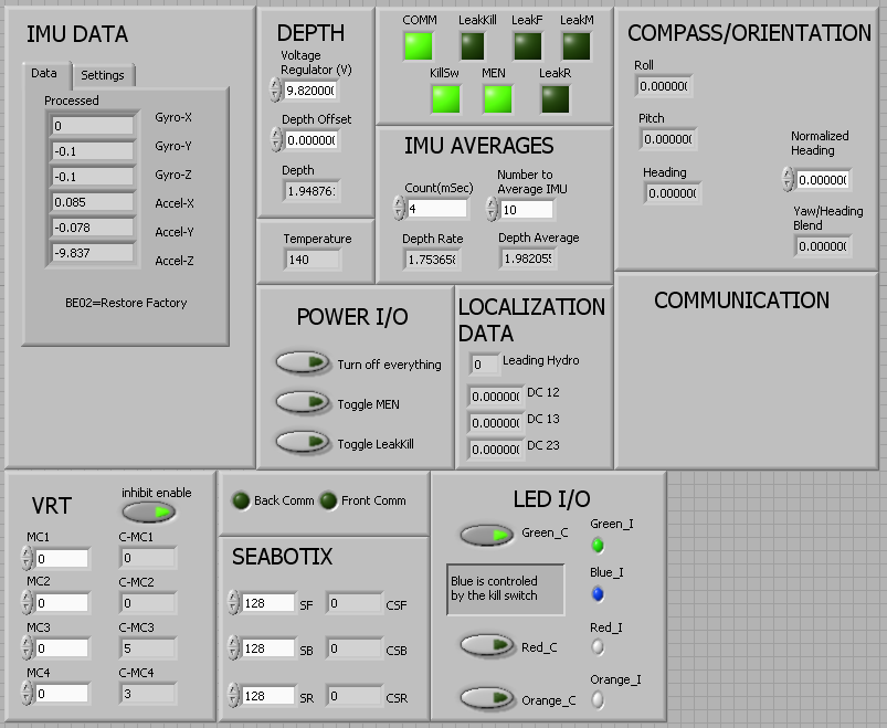
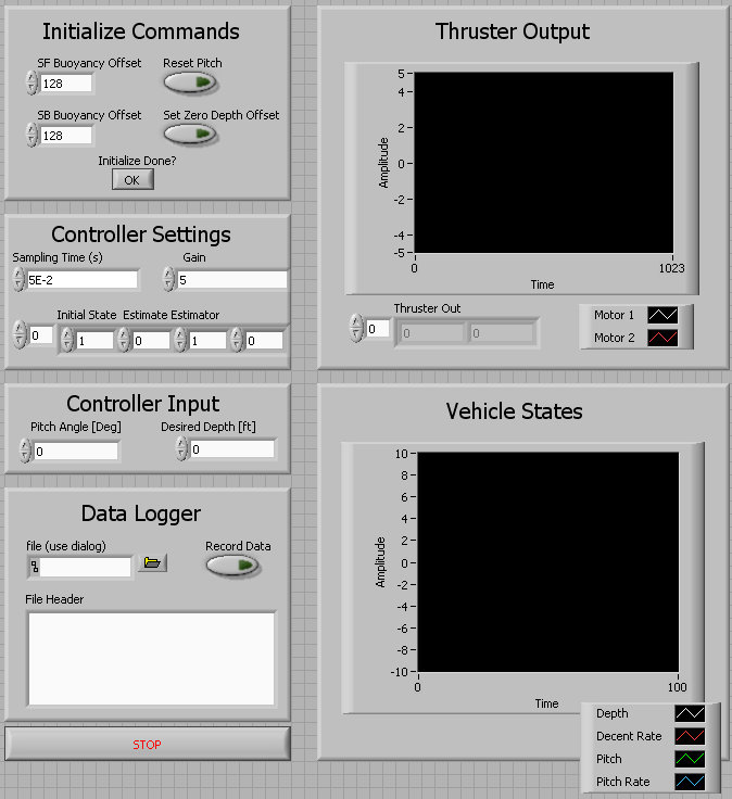
Below is a picture of the main FPGA front panel.
The Ultra-Short Baseline (USBL) localization method determines the position of the vehicle in three-dimensional space with respect to an underwater beacon. AUVSI's AUV annual competition is the primary motivation for the development of the underwater localization system. The primary goal of the AUVSI AUV competition is to have an underwater vehicle find, locate and surface directly above an underwater beacon placed at an unknown location in a 60 meter diameter anechoic Naval testing facility. The secondary motivation of the underwater localization system is to give the KRAKEN vehicle (and future underwater vehicles) an "underwater global positioning system".
The localization method uses a change of basis algorithm to calculate the azimuth and elevation of the vehicle with respect to an underwater acoustic beacon. By using the depth and heading measurements by the vehicle's on board sensors, a fixed position in inertial space can be determined. The USBL algorithm is based on an assigned body fixed frame [S] to the vehicle, where [S] is a right handed coordinate system such that S3 points upwards through the vehicle. A line of sight vector is defined from the hydrophone array (located on the bottom of the vehicle) to the underwater acoustic beacon placed near the Command Module. The line of sight vector is designated e_T and can be seen below.
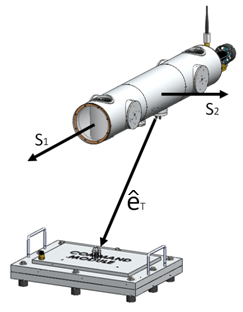
The line of sight vector is a unit vector showing only direction and is calculated from the azimuth and elevation of the vehicle with respect to the acoustic beacon. The elevation angle (El) is the defined as the angle between the plane spanned by S1 and S2 and the line of sight vector. The azimuth angle (Az) is defined as the angle between the S1 axis and the projection of the line of sight vector on the S1 S2 plane. This angle is defined clockwise between 0 and 360 degrees. Using these definitions for azimuth and elevation, a definition for eT in e space can be developed as:

Since the line of sight vector is established in terms of the azimuth and elevation angles it can be related to the signals received by the hydrophone array on the vehicle. In order to correctly determine the azimuth and elevation from the signals, the configuration of the hydrophone array must be predefined, depicted by the diagram below.
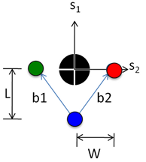
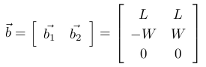
The directions of S1 and S2 indicate that the above diagram is a bottom view of the vehicle. The two hydrophones are placed in parallel with the S2 axis forward of a single hydrophone located along the S1 axis. W specifies the distance between the aft hydrophone with the fore hydrophone in the S2 direction. L specifies the distance between the aft hydrophone with the fore hydrophones in the S1 direction. The two b vectors are position vectors of the two fore hydrophones with respect to the aft unit and can be described as:
The difference in distance from the pinger to each hydrophone y can be calculated by using the time delay of arrival of the signal and the speed of sound propagation in water as:
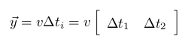
where ∆ti is the time difference across bi .The speed of sound propagation in water is designated v. The difference in distance can then be determined by taking the projection of b onto e_T.

The above equation represents the transformation from the body frame to the inertial frame. Using this equality, the azimuth and elevation angles are solved and equal:
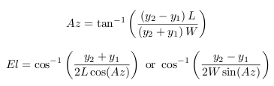
Due to the cases that produce imaginary or undefined results for the elevation angle, two equations are used. The larger denominator is chosen to avoid imaginary or infinite solutions. Once azimuth and elevation are known there exists a “cone” of possible vehicle locations with the vertex centered at the Command Module (Figure (a) below). The depth sensor is used to determine the height of the vehicle on the localization cone, constraining it to a circle of possible vehicle orientations, Figure (b) below.
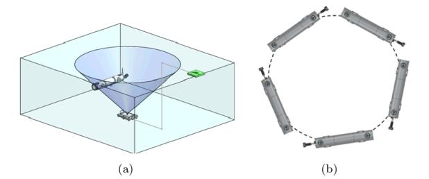
Every position along the circle has a unique heading associated with it. By using the earth’s magnetic field as an absolute reference frame, the on-board magnetometer measures absolute heading, constraining the vehicle to single point on the circle. Since the magnetometer uses the Earth’s magnetic field as reference, the global frame that the vehicle locates within is oriented with magnetic north. Depending on the orientation of the pool with respect to the magnetic field, an axis rotation may be required to align the global frame with the local pool frame.
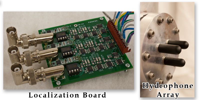
The analog signals from the three hydrophones are read simultaneously using the NI9215 4-channel simultaneous sample analog input module in place on the vehicle cRIO. The samples are used to digitally reconstruct the signals such that their frequency and phase differences can be caluculated using different sub vi's. The phase difference between the signals is then used in conjuncture with the frequency of the signal to calculate the time difference of arrival of the three signals. The time difference of arrival is the used with the aforementioned technique to calculate the vehicles position with respect to the acoustic beacon.
Underwater acoustic communication plays a vital role in CUBOAT project. Due to the physical properties of water typical wireless communication techniques are impractical and existing underwater wireless transmission hardware is both very large and very expensive. The most commonly used underwater modem was developed by the Woods Hole Oceanographic Institute and costs several thousand dollars. The CUBOAT project designed, built tested and verified a fully functional underwater wireless modem for less than $500 total hardware costs. Communication is defined as two-way data transfer between nodes using in-house modem designs and inexpensive underwater transducers to send frequency modulated data packets as shown below.
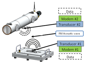
The modem is designed to achieve a data transfer rate of 100 bits/sec using a pulsed data protocol to mitigate reverberation issues. The modem board functional block diagram below depicts the hydrophone `H', the signal receiver, and the fish finder transducer `FF' used to send the signal.
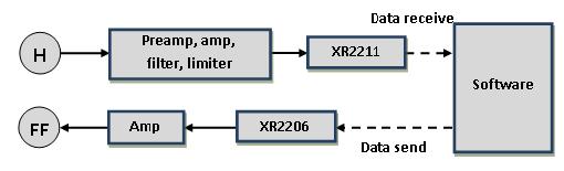
The XR2211 and XR2206 blocks are specialized inexpensive demodulation and modulation chips manufactured by Exar communications. The software acts as a data buffer, determining the correct time to send a single bit to the XR2206 block for modulation. After acoustic transmission, the XR2211 chip demodulates the analog signal on the receiver and passes on the digital signal to the software. The software buffers the incoming signal until the entire data packet has been received. Once the complete packet has been received, the software extracts relevant information.
In order to send a binary signal, the XR2206 chip must modulate a digital high/low to two separate frequencies chosen to be 15 kHz and 20 kHz to minimize the attenuation of the water and maximize the effectiveness of the hydrophone preamplifier. The XR2206 interfaces with the command module's software running LabVIEW through the NI USB-DAQ 6501. This modulated signal is then amplified to 25 Vpp and broadcast by the transducer. The signal is heavily attenuated as it travels through the water and be amplified and filtered after being received by the hydrophone. The hydrophone on the receiving end has a high impedance which must be matched by a preamplifier. The analog signal is fed into the XR2211 chip which is centered at 17.5 kHz. The lower incoming signal, 15 kHz, is demodulated to a digital low, while the higher signal of 20 kHz is demodulated to a digital high. The output of the XR2211 demodulation chip is read directly by the NI 9401 digital I/O module stationed on the vehicle's cRIO. The vehicle's software is then used to process the incoming signal.
The software that runs the communication on both the Command Module and vehicle is written in LabVIEW. The Command Module software was housed on the laptop while the vehicle software ran on the cRIO. The software builds each communication packet that is sent. The packet consists of a four bit message type, a data section (of varying length), and checksum. The software then communicates to the XR2206 chip what frequency to send out at the specified baud rate. The receiving software waits until a high signal (start bit) is recieved, and then samples at the correct frequency to receive the signal. Packets of different lengths were sent, so knowing how long to read for was crucial. The software would first read in the first four bits of the packet, which specified which type of packet it was. Then the software would continue reading, based on the known lenght of the prescribed packet type. Once the full packet is received, the checksum is recalculated to make sure there was no error in the communication. If there was no error, then the software would extract the relevant data contained in the packet, and pass it on to the appropriate system.
The following video shows the communication vi frontpanel running in real-time during a field test. The right side indicators represent a sample number of bits to be transmitted one at a time in 4 bit bursts by the command module's sending hardware. The indicators on the right side show the individual bits received and interpreted by the vehicle's receiving hardware and software.
The KRAKEN vehicle contains six degrees of freedom, five of which are controllable. The six degrees of freedom are surge, sway, depth, roll, pitch and yaw. Roll is considered passively stable because the center of gravity is below the center of buoyancy of the vehicle, which creates restoring moments when roll perturbations occur. Modern control theory was used to model the dynamics of the vehicle or plant and to develop the state space controllers for each mode. Due to the lack of C programming knowledge and software-hardware interface complexity, the CUBOAT team decided that the vehicle controllers would be written in LabVIEW. The controllers also utilize the onboard sensor package and vehicle actuators/thrusters. The software was written on the cRIO so that the built in control and state space functions in LabVIEW could be maximized.
The sensor inputs are fed to the controller through the cRIO FPGA interface and read by the controller. The controller computes the new motor controller step voltage values which are then sent to the motor controller boards located on the vehicle. This process occurs in a control loop so that the vehicle maintains its desired position/location. The NI components and LabVIEW software used on the CUBOAT project has provided the team with easy software-hardware implementation for very complex vehicle controllers. Below is an example of the depth/pitch multiple input – multiple output (MIMO) controller VI.
Finally, control simulations were matched with experimental results (captured by a FPGA sensor data logger) for the depth/pitch mode and the yaw mode controllers and are shown below.
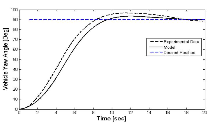

Currently the team is designing a more accurate nonlinear control model of the vehicle. Additionally, a fully coupled controller is proposed for future vehicle implementation.
Final Project Video
