- Document History
- Subscribe to RSS Feed
- Mark as New
- Mark as Read
- Bookmark
- Subscribe
- Printer Friendly Page
- Report to a Moderator
- Subscribe to RSS Feed
- Mark as New
- Mark as Read
- Bookmark
- Subscribe
- Printer Friendly Page
- Report to a Moderator
Before opening this example, make sure toinstall the LabVIEW Interface for Arduino.
Description:
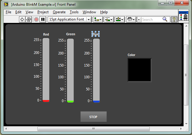
This example shows how to use color sliders in LabVIEW to control a BlinkM.
You can purchase BlinkM's here: http://www.sparkfun.com/products/8579
Tutorial:
- Make sure you have installed the LabVIEW Interface for Arduino.
- Download the Attached VI.
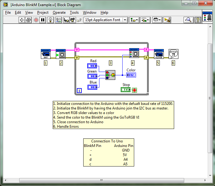
- Make sure you have the BlinkM connected to your Arduino as described on the block diagram comment.
- Click Run.
- Move the sliders and watch the BlinkM change colors.
- Mark as Read
- Mark as New
- Bookmark
- Permalink
- Report to a Moderator
Nice example. One question: With the BlinkM via the standard library BlinkM_funcs.h you can set pins A2 and A3 to act as GND and PWR respectively. Is there a way to use the LIFA to set these parameters or does this need to happen as part of custom "firmware" code? (easy enough to do in the Arduino IDE but it would be nice to understand how to do this in LIFA...)
- Mark as Read
- Mark as New
- Bookmark
- Permalink
- Report to a Moderator
Jolt,
This was not implemented in LIFA since LIFA is not using the Arduino BlinkM Libraries. I built the BlinkM VIs using LIFAs generic I2C comands as an example of how you can add any I2C device without having to modify the firmware.
When you say set A2 and A3 do you mean the analog inputs on the Arduino? Either way you should have no problem adding this to the firmware. If you do so please post the code bits in LV and Arduino that you used so others can learn from it.
Thanks!
-Sam
LIFA Developer
- Mark as Read
- Mark as New
- Bookmark
- Permalink
- Report to a Moderator
Hi Sam,
Yup, the BlinkM (as purchased with it's own little PCB) can be plugged directly into the Arduino such that I2C pin "-" goes to A2, "+" goes to A3, "d" goes to A4, and "c" goes to A5.
The BlinkM_funcs.h library sets A2 and A3 to act as power pins. To be honest I don't really understand how the library does this but I will excerpt the code below.
If you want to use or port anything from the BlinkM library it all can be found here http://code.google.com/p/blinkm-projects/downloads/list
Taking and slightly modifying the code to get the "power pins" functionallity described above simply add some code to setup() in the Arduino "firmware".
void setup()
{
// Initialize Serial Port With The Default Baud Rate
syncLV();
// Additions to initialize BlinkM power pins
// PORTC3 becomes PWR and PORT2 becomes GND
DDRC |= _BV(PORTC3) | _BV(PORTC2); // make outputs
PORTC &=~ _BV(PORTC2);
PORTC |= _BV(PORTC3);
delay(100); // wait for things to stabilize
Wire.begin();
Wire.beginTransmission( 0x09 ); // assumes default I2C address...
Wire.send('o'); // stops the default "script" on the BlinkM
Wire.endTransmission();
}
- Mark as Read
- Mark as New
- Bookmark
- Permalink
- Report to a Moderator
Jolt,
This works becuase on the Atmel328 the Analog input pints are (I assume) multiplexed with GPOI pins. The code you use to set them to '+' and '-' probably disables the analog input, sets them to DIO, and sets one high and the other low. This is fine, but keep in mind that you cannot use them as analog inputs as long as this code is inplace (even if you decide not to use the blinkm). You may want to instead a command (in the LIFA case structure) that enables / disables this functionality.
-Sam
LIFA Developer
- Mark as Read
- Mark as New
- Bookmark
- Permalink
- Report to a Moderator
Hi Sam,
I think you are right r.e. the pin setting - I wasn't too concerned because I will probably be using at least slightly custom code on the Arduino for any given project (always a hybrid, albeit with a big chunk abstracted via the LIFA).
I wasn't planning on jumping into modifying the LIFA case structure/packet system quite yet but that does sound like a good idea.
Cheers,
