- Document History
- Subscribe to RSS Feed
- Mark as New
- Mark as Read
- Bookmark
- Subscribe
- Printer Friendly Page
- Report to a Moderator
- Subscribe to RSS Feed
- Mark as New
- Mark as Read
- Bookmark
- Subscribe
- Printer Friendly Page
- Report to a Moderator
Contact Information
University: The University of Texas at Austin
Team Member(s): Barret Hendricks, Alex Luecke and Jody Van Reet
Faculty Advisors: Dr. Richard Crawford and Dr. Raul Longoria
Email Address: barrethendricks@hotmail.com, aluecke07@gmail.com, jmvanreet@gmail.com
Project Information
Title: Development of a Pool-Playing Robot Using National Instruments' Robotics Starter Kit
Description:
Beginning with the National Instruments’ robotics starter kit, we created a robot that can execute up to five pool shots as directed by a user. Our project involved designing and manufacturing a rotatable cue mechanism, creating a user interface, and developing VIs to control the actions of the robot and to visually identify pool balls on the table.
Products:
LabVIEW 2010 including:
FPGA
RealTime
Vision
NI Robotics Starter Kit with sbRIO9631
The Challenge:
The object of our project was to demonstrate the capabilities of the National Instruments’ robotics starter kit by implementing a pool-playing robot. Our goal for the robot was to have it autonomously shoot up to five pool balls into pockets selected by a user. We built upon work completed by another group of engineering students at The University of Texas. They had successfully reconfigured the wheels and motors of the robot to allow it to move linearly along a rail mounted to one side of the pool table.
For this project we were required to use LabVIEW’s vision capabilities to identify three to five solid colored pool balls on a table, create a user interface that would allow an individual to select a pocket for each of the pool balls identified, and develop a mechanical apparatus for executing shots in two dimensions.
The Solution:
In order to complete our project, we needed to mechanically modify the Robotics Starter Kit by adding cue actuation and rotation mechanisms. We implemented the cue actuation using a cam and spring plunger and achieved the rotation by using a chain and sprocket system. Electrical work included installing stop sensors so the robot could calibrate its position along the side of the pool table, adding a wireless network and supplying power to the added devices.
The actions of the robot were primarily controlled by our RT_Main VI running on the sbRIO. Each individual action of the robot is encapsulated in a panel of a flat sequence structure within the VI, facilitating simple sequential operation. We used VIs from LabVIEW’s Vision development module and an Ethernet camera mounted on the robot to identify billiard balls by color. Communication between the sbRIO and host PC was conducted using network streams. Details of the different design components are expanded upon below.
 Figure 1. Completed robot on pool table
Mechanical Design
After considering many options, we chose to use a spring potential energy system to replicate the action of a pool cue. Our design involves a spring attached to a pool cue shaft which is compressed by a rotating cam. Once the cam rotates to a certain point, it releases the spring, which drives the shaft forward and transfers energy to the ball. In order to contact the ball midway through the cue’s stroke, we programmed the robot to pre-load the cue before approaching a billiard ball. In this way, the force of the spring is applied to the ball over a longer period of time, resulting in a greater initial velocity.
Our team was unable to find existing mechanical systems that would accomplish the task of striking a billiard ball, so our team had to design, machine, and assemble every part of the cue mechanism. We attempted to make the parts as manufacturable and repeatable as possible with each part designed to be easily machined. We tried to maintain a uniform bolt size and to keep bolt insertion points on one side of the structure for simple assembly. The completed cue mechanism is pictured in Figure 2.
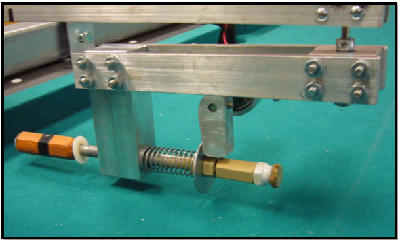
Figure 2.Optimized Cue Mechanism Design.
After machining all of the required parts, the team next tested available springs to optimize the performance of the cue mechanism. The results of this testing can be seen in Figure 3, which graphs ball travel versus spring stiffness. Due to the limited torque available from the motor, one ofthe springs tested could not be compressed by the cam. The team chose the spring which gave the greatest ball travel distance and was still able to be compressed using the motor and cam.
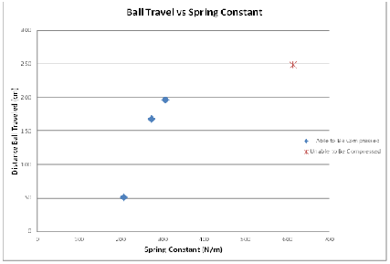
Figure 3. Graph of SpringTest Results.
We chose to locate the axis of cue rotation above the billiard balls at the end of the arm, effectively separating the tasks of properly positioning the robot along the rail and rotating the cue mechanism. This means that the linear motion of the robot and the angular rotation of the cue mechanism can be executed independently of each other, greatly simplifying the necessary calculations.
The arm which supports the cue mechanism was fairly easy to fabricate and install as it is merely two aluminum bars of equal length attached to the robot. For the rotation device, the team ordered chain and sprocket parts from Pitsco. The team chose to install a large sprocket onto the cue mechanism and a small sprocket onto the rotation motor in order to gain a mechanical advantage for better resolution in the robot’s angle calculations.
Electrical Design
We faced a number of electrical challenges while getting the cue and rotation mechanisms to work properly and interface with the software. Electrical work included setting up a wireless network between the host computer and robot, wiring stop sensors to the robot, installing a second motor controller drive and powering the devices.
Network
Because both the robot and camera connect to the laptop through Ethernet connections,and because the motion of the robot would make use of cables to the laptop extremely unwieldy, we needed to create a wireless network through which communication between laptop and project components can be routed. We ordered an ASUS 330-gE four function wireless router for our project. The ASUS 330-gE served as a wireless access point (WAP), allowing the computer to connect wirelessly to a remote network. When the WAP arrived, we realized that it only had a single Ethernet port. In order to connect both the camera and sbRIO to the WAP, we used the local area connection capability of a D-Link router. In all, our network involved five major components: the host computer, the sbRIO, the Ethernet camera, the D-Link router and the wireless access point. The wireless access point was used to broadcast a signal so that the host computer could connect wirelessly to the network. Eventually, the router and wireless access point were both mounted to the robot. Using this method, there were no Ethernet cables tethering the robot to the outside world. The router and access point are pictured in Figure 4.
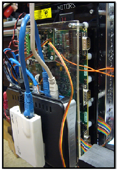
Figure 4. Wireless access point and router mounted to robot.
Stop Sensors
For stop sensors, our team purchased simple push-button switches. When compressed, the sensors complete the circuit between their posts. The digital input/output pins onthe sbRIO detect a threshold voltage that can be interpreted as a true/false Boolean. From testing, our group found that, by default, the pins carry a voltage above the threshold voltage. The FPGA interprets the default voltage as true. When the digital I/O is connected to ground, the FPGA reads a false value. By connecting one post of the push-button to ground and the other post to the digital I/O port, the FPGA can detect if the push-button switch is open or closed. The Boolean outputs from the left and right stop sensors were then used in the operation of the robot.
Additional Motor Drive
Out of the box, the RoboticsStarter Kit supports two motors and two encoders. In order to add another encoder, the wires from the encoder are attached to certain pins on the sbRIO. However, in order to add another motor, the motor must be connected to a motor drive board, which is then connected to pins on the sbRIO. The additional motor drive interjected extra complications into the project. First, we were required to provide additional power to the motor drive. We spliced the power cables from the first board to power the second. When the motor switch is turned on, both motor drives receive power. Besides the issue of power, the group relied on expert counsel from an engineer at NI in order to determine how to connect the motor drive to the pins on the sbRIO. The wires were connected accordingly, and subsequent testing verified the connections were functioning as intended.
Powering Devices
The Ethernet camera, router, and wireless access point were originally powered by cables that connected to conventional AC wall sockets. When in use, the robot’s motion was constrained by the length of the power cables. In order to remove the tethers, our team connected the devices to run off the robot’s battery supply. The power wires for all three devices were cut and spliced together. Then, they were connected to a plug that would fit over +5V and GND pins on the sbRIO. When the plug is connected, all three devices draw their power from the board.
External Power Supply
Since the battery was required to power an additional motor drive as well as three external electrical devices, the charge life significantly decreased. During our testing phases, we were inhibited by downtime for battery charging. Under recommendations from our faculty advisor, Dr. Longoria, we used an external power supply to provide 12 volts to the robot. Our team purchased banana plugs to connect to the power supply and connectors to attach to the power plug from the robot. We used a long section of wire in order to not constrain the linear travel of the robot. Once the power supply was connected, we were able test for extended periods of time without interruption.
Software Design
Generating software to automate the robotics tasks proved to be one of the project’s most daunting challenges. Code needed to be specifically written to handle Vision tasks, the Real Time operation of the robot, and the Field Programmable Gate Array (FPGA) interfaces.
The final code necessary to operate the robot includes the FPGA VI, the Real Time VI and three vision VIs. These VIs are included with this paper as attachments. Many additional VIs were developed over the course of the project to test portions of the code as it was being written. The following sections detail our work on the various different aspects of software development.
FPGA Modifications
The FPGA code was adapted from the existing FPGA code, originally written by engineers at NI. The modification consisted of adding support for a third motor and encoder and adding code for the two stop sensors. Code for the third motor and encoder was copied from the existing motor and encoder and was organized and wired exactly as with the previous motors. The stop sensors were each provided with an FPGA reference for signal I/O. The output for the stop sensors is a simple Boolean value: false when activated and true when not activated.
RealTime Code
The real time program was developed from scratch, with no code reused from the previous group. We’ve organized the code using a flat sequence structure; each panel of the flat sequence is carried out in its entirety before the code contained within the following panel is executed. The following paragraphs outline the functionality of code, panel by panel. Each of the panels contains one or more FPGA reference nodes. It should be noted that whenever we describe setting the pulse width of the motors or reading the motor encoder position, the values of interest are wired through the FPGA reference nodes. Figure 5 shows a flow chart of the real time code.
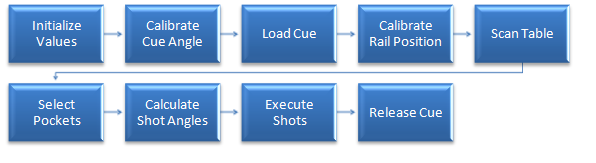
Figure 5. Flow Chart of Real Time Code
The first panel of the program simply initializes all user controls to their default values and sets the pulse widths of all three motors to a value that will cause the motor to stop. The second panel of the program contains the code to prompt the user to calibrate the cue to an angle of zero degrees and then initiate the start of the vision scan. The user adjusts the cue via a slider on the front panel until the cue is aligned at zero degrees. When the user presses the 'Aligned' and 'Scan' buttons, the program moves to the third panel where the robot preloads the cue mechanism.
In the fourth panel, the program sets the pulse width on the drive motor to a value that will cause the robot to move left. When the left stop sensor is activated, the robot stops.The fifth panel of the program constitutes the Vision scan. Two while loops operate in parallel within this panel. The first controls the motion of the robot along the rail, directing the robot to move to the right. The second while loop facilitates communication with the host computer and stores the results of vision processing. When a ball is detected, a string identifying the ball and the encoder position marking the location of the ball are added to arrays. The encoder position corresponding to the ball is adjusted to account for the offset of the camera relative to the cue tip.
The user chooses destination pockets for each pool ball within the sixth panel ofthe real time VI. Drop down controls containing pocket options (left, center and right) are embedded in a while loop which essentially halts the program until the usermakes a selection. The selections from the drop down menus are passed, along with the array of rail motion encoder positions, to the seventh panel which is comprised entirely of a MathScript node that calculates the necessary cue angles for each ball. We hard-coded values for the positions of each pocket and the perpendicular distance of the pool balls from the edge of the rail. The result of the MathScript node is an array of doubles representing the necessary cue angle for each of the balls.
The main structure of the eighth panel consists of a for loop (to be executed once for each ball/encoder position/cue angle in the incoming arrays) which further embeds a five panel flat sequence structure. The first embedded panel directs the robot to move to the position of each of the detected balls and the second embedded panel rotates the cue to the desired angle. The third embedded panel actuates the cue mechanism. The pulse width of the actuation motor is initialized to a value that will cause the motor to rotate in the correct direction and activate the cue. The fourth embedded panel preloads the cue mechanism to prepare the robot for the next shot.The final embedded panel rotates the cue back to an angle of zero.
The final action programmed in the real time code is the release of the cue mechanism. The pulse width of the cue actuation motor is set to a value thatwill cause the cam to rotate away from the spring, preventing undue stress onthe motor.
Calibration
In order to accurately control the motion of the robot along the rail and rotation of the arm, we needed to determine conversion factors between encoder units and distance in centimeters and angle in degrees. Using the front panel of the FPGA VI, one group member controlled the rail motion motor and rotation motor while the remaining group members measured resulting distance or angle and recorded results. Results of the calibration have been incorporated into the real time code.
Vision
Thereal time code governing the actions of the robot is only meaningful given correct acquisition and interpretation of external signals. Our implementation of the pool-playing robot relies on an Ethernet camera to acquire information from the environment. The challenge we faced was to develop code that could interpret the images from the camera and translate these images into useable data for the robot. We wrote three main VIs to accomplish this task: RobotVision.vi, ImageProcess.vi and VisionTrainer.vi.
Robot Vision VI
The bulk of the image manipulation and processing takes place in the RobotVision VI.The inputs to the VI include the image captured from the camera as well as acolor classifier file path and two predefined search regions. The search regions correspond to the area of the image where a billiard ball would beexpected to appear. Outputs from the VI include a Boolean value indicating whether a ball was detected, the ball number(zero for cue ball and one through eight corresponding to the different solid colored balls), the ball radius, measured in pixels, and the X-coordinate ofthe ball center, also measured in pixels.
Creating a VI that could generate the desired outputs given the inputs consisted of a great deal of experimentation with the Vision development module. Many VI’s wereconsidered for the primary purpose of identifying pool balls on the table, and were rejected as problems arose. Ultimately, a call to the NI Technical Support division brought us to the Vision Assistant. The NI representative guided usthrough a number of processing operations and helped us to chart out a path totake to achieve our vision goals.
The first step of the vision processing is to distinguish between the pool table and potential billiard balls by examining color within a rectangular region ofinterest (ROI). We chose to use color classification to identify colors fromthe ROI rather than trying to sort through red green blue (RGB) values. The color classification VIs, provided with the Vision Development Module, comparethe color from the image to various samples stored in a previously generated classification file. If the color from the ROI matches one of the pool ball colors with a reasonable degree of certainty, the RobotVision VI proceeds tothe next processing step. If the color from the ROI is identified as that ofthe table, the RobotVision VI skips the remaining processing steps and returns a ‘FALSE’ value to the calling VI.
The next processing operation is color thresholding, which converts the source image from a 32-bit RGB image into a binary image. The color thresholding VI sets the value of a pixel in the binary image based on preset maximum and minimum values for each of the red, green and blue components of a pixel. If the pixel value falls within the acceptable range, the value of resulting pixel in the binary image is one, while all the pixels outside the thresholding range become zero. A binary conversion is advantageous because the edge detection VI is able to search for a simple switch from zero to one instead of dealing with three different color components, each with 256 possible values.
The third processing operation is to smooth out the image. Because the pool table will be located in a non-ideal environment, shadows and glares affect the clarity of the image. The thresholding operation may not clearly separate the balls from the table because the table and balls are not comprised of a uniform color. The smoothing process essentially removes some of the noise from theimage by filling in outlier pixels.
The final processing step uses the Find Circular Edge VI. This VI searches an annular ROI, starting from the outer radius and moving inward, for points where the pixel value switches from zero to one and uses these points to fit a circle. The Find Circular Edge VI identifies the position of the center of the circle and the radius of the circle, and, provided the fit circle has a radius consistent with that of a pool ball, the RobotVision VI outputs these values to the calling VI along with a ‘TRUE’ Boolean indicating a ball has been found.The results of all processing steps are shown in Figure 6.
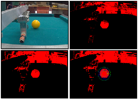 Figure 6. The original image (top left) followed by the results of thresholding (top right), smoothing (bottom left) and circular edge detection (bottom right).
Image Process VI
The calling VI for RobotVision is the second of three VIs developed to handle vision processing: ImageProcess.vi. All image capture functionality, communication between host computer and robot, and interaction between computer and user occur within this VI.
Continuous grab from the camera was set up using VIs from the IMAQdx menu. Images from the camera are stored in a buffer and continuously displayed on the front panel, so the user can always see the view from the robot’s perspective. The VI pulls images from the buffer and passes them to the RobotVision VI, which is included as a sub VI. Results from the RobotVision VI are communicated back to the robot using network streams, described in detail later in this paper.
Before image capture commences, the ImageProcess VI allows the user to set the robot’s IP address and gives him the option to select an existing classifier file or create a new classifier file. If the user chooses to create a new classifier file, the ImageProcess VI opens the VisionTrainer VI via ‘Invoke VI’ nodes.
Vision Trainer VI
During testing of the pool-playing robot, we observed that the Vision code more correctly identified balls at certain times of the day. We were able to determine that lighting conditions strongly influenced how accurately the Color Classification step of the RobotVision VI matched images to color samples. Because we had no way to set up a color classifier file that would match the conditions at use, we chose to develop a VI that would allow the user to create a classifier file at run time.
We wrote the VisionTrainer VI to be highly event driven as all functionality is tied to user interaction with the front panel. From the front panel, the useri s able to add classes for each of the balls via text box and ‘OK’ button and select from these classes using a drop down menu control. A live camera feed is displayed to the front panel and is overlain with a circle that exactly matches the annular ROI used in the Robot Vision VI. Once the user positions a ball within the circle, he simply clicks the ‘Add Sample’ button to assign a color sample to the selected class. A file dialog prompts the user to save the classification file upon exiting the VI.
Network Streams
Network streams work by sending data between reader and writer endpoints over the existing wireless network. We set up reader and writer endpoints in both the real time code and the ImageProcess.vi. During the vision scan, the real time code writes the encoder position to the network stream which is then read by the ImageProcess VI. After the RobotVision VI executes, the ImageProcess VI writes the passed in encoder position, along with the ball found Boolean, radius and X-coordinate of the ball center to the network stream to be read by the real time code.
Video of Completed Project:
- Mark as Read
- Mark as New
- Bookmark
- Permalink
- Report to a Moderator
Hello jvan,
Thank you so much for your project submission into the NI LabVIEW Student Design Competition. It's great to see your enthusiasm for NI LabVIEW! Make sure you share your project URL with your peers and faculty so you can collect votes for your project and win. Collecting the most "likes" gives you the opportunity to win cash prizes for your project submission. If you or your friends have any questions about how to go about "voting" for your project, tell them to read this brief document (https://forums.ni.com/t5/Student-Projects/How-to-Vote-for-LabVIEW-Student-Design-Projects-doc/ta-p/3...).
I'm curious to know, what's your favorite part about using LabVIEW and how did you hear about the competition? Nice work with the NI myDAQ!
Good Luck, Jessica in Austin, TX.
