- Document History
- Subscribe to RSS Feed
- Mark as New
- Mark as Read
- Bookmark
- Subscribe
- Printer Friendly Page
- Report to a Moderator
- Subscribe to RSS Feed
- Mark as New
- Mark as Read
- Bookmark
- Subscribe
- Printer Friendly Page
- Report to a Moderator
Development of Microrobotics Control System - UT Arlington Microrobotics Team
Contact Information
Next Gen Systems Research Lab,
University of Texas, Arlington
NH 250, 416 Yates Street, Arlington, TX 76011, 817-272-3342
Team Member(s): Muhammed Rashid Pac
Kunal Raithatha
Justry Weir
Brian Rukavina
Faculty Advisors : Dr. Dan Popa
Email Address : popa@uta.edu, mpac@uta.edu
Project Information:
Title:
LabVIEW- based microrobotic control system.
Description:
Microrobots are envisaged to be useful in many future applications such as nanomanufacturing, in-vivo surgical procedures, as well as covert military surveillance. The objective of this project is to develop a control system for simulation and implementation of microrobots. The system was used by UT Arlington’s microrobotics team to compete at the NIST Microrobotics Challenge held in Shanghai, China, May 9-13, 2011.
Products:
Software:
LabVIEW - Control Design and Simulation, 3D Picture Control, FPGA, Vision Assistant, Vision Builder for Automated Inspection, NI Scope
Hardware:
NI PXI-8196 Embedded Controller for PXI 1042 chassis, PXI 7831 FPGA RIO, PXI-5122 (Scope), PXI-5121 (Arbitrary Waveform Generator), PXI-6251 (DAQ), NI 1742 Smart Camera
The Challenge:
Controlling microrobots with sizes less than a millimeter requires tight real-time integration of visual microscopic images and signals for generating actuation fields via robust control strategies. Motion control at the micro and nanoscale is more challenging due to increased uncertainties stemming from manufacturing errors, surface effects such as stiction and adhesion, environmental conditions such as humidity and temperature variations, and decreased sensor signal vs. noise ratios. In order to mitigate these challenges, simulation and visualization tools must be used prior to hardware implementation. Designs of the microrobots are based on the selected power delivery scheme and necessitate a particularly close relationship with the rest of the control system. Selection of appropriate equipment for the system setup is guided by the microscale precision requirements. The overall system requires high-resolution image acquisition, real time processing of the image, extraction of the key variables for the control system, and generation of actuation signals.
The Solution:
The overall control system setup required for robot actuation is as shown in Figure1. The microrobot and arena are imaged using the microscope camera; then the information is relayed to the computer. Image stream is acquired from the camera and processed in real-time to extract position and velocity information of the microrobot. The pose of the robot is used in the trajectory control to generate the necessary signal, which subsequently drives the piezoelectric transducer underneath the arena. Figure 7 in later section depicts overall closed-loop control system architecture and also names National Instruments hardware integration in this project.

Figure 1 Controls setup for Vibration driven microrobot
The tasks associated with the technical aspects of the project are divided into four main categories and summarized as follows:
1. System Design, Modeling, and Simulation:
Formal modeling of overall systems is carried out via a mathematical model, which attempts to find analytical solution to predict behavior of the microrobot for a set of parameters and initial conditions. Early phase of the project was to simulate forces in robot legs and corresponding robot position in response to actuation signal primarily using LabVIEW Control Design and Simulation module as shown in Figure 2 followed by animation of proposed robot design using 3D Picture Control toolkit as shown in Figure 3. Other software packages used during this project were Sugar, SolidWorks and ANSYS.
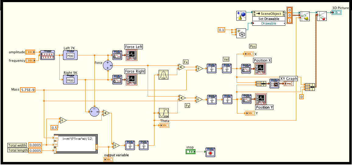
Figure 2 Simulation in Control design and Simulation loop LabVIEW
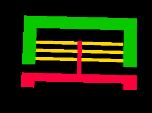
Figure 3 Microrobot animation using 3D Picture Control
2. Microrobotand Arena Fabrication:
At NIST microrobotics challenge we made use of microrobots, which are powered and controlled through wireless transmission of vibration energy. Microelectromechanical (MEMS) based microrobots are fabricated on 4” Silicon Insulator Wafers (SOI), using silicon-processing techniques including lithography and reactive ion etching at UTA NanoFabrication facility. Approximate dimensions of a robot is 450 μm x 450μm x 10 μm, reaching speeds up to 10 mm/s. Designs vary based on the number of legs, size of main body, design and orientation of the springs used, and the size of the masses attached to the springs. These designs utilize the modes of spring’s resonant frequencies to generate motion. In Figure 4 are different designs of robots secured to the wafer using breakable tethers.

Figure 4 SEM pictures of ViBOT designs fabricatedat UTA’s Nanofab
3. Image Processing and Control Development:
In order to measure microscopic changes in the microrobot’s position; cameras with high-resolution image sensor, greater field of view, and real time data transfer are necessary. To gather data of x, y, and angular position NI SMART camera acquires and processes real time images of a microrobot, In our project 1/3” CCD sensor, 60 frames per secondSMART camera running Vision Builder for Automated Inspection is interfaced to NI PXI-8196 Embedded Controllerfor PXI 1042 chassis.
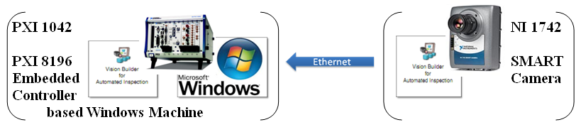
Figure 5 SMART Camera connection with PXI 1042 Chassis
Robot position, which is also a feedback signal to determine magnitude and frequency of the driving signal for the vibration generator is obtained from “Vision Builder for Automated Inspection (VBAI)” image-processing functions. The figures 6(a) through 6(c) below show the four-step process used to get x, y position and angle theta of microrobot using “Vision Builder for Automated Inspection”.
Step1. Image acquisition: - It is the first step after configuring the camera to acquire continuous images of microrobot. SMART camera provides 60 frames per second and has an option to change exposure time and gain in order to change light intensity of image.
Step2. Template Selection: - For every robot design a template is defined, which is a pre-captured image of the robot to be searched inside a live image. Multiple templates can also be searched and processed.
Step3. Find Coordinates: - VBAI first searches the template pattern inside the live image and once the template is located it provides the coordinates of the detected robot. Once we define the boundaries of the arena in VBAI for known arena size in micrometers, position values can be calibrated to micrometer from default pixel values.

Figure 6(a) Image Acquisition
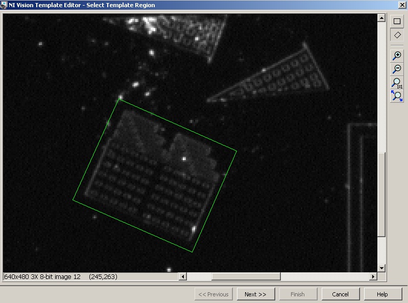
Figure 6(b) Template Selection
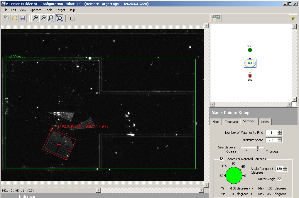
Figure 6(c) Find Coordinates
4. SystemSetup and Integration:
The project integrates different National Instruments hardware to perform sensing, processing and actuating. NI SMART camera serves not only as the image sensor but also as a processor for locating the robot in an image. PXI 7831 reconfigurable I/O with custom FPGA logic or PXI 5121 Arbitrary Waveform Generator is used to generate square wave for driving the piezoelectric actuator.
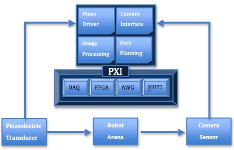
Figure 7 System Overview
NI PXI-8196 Embedded Controller for PXI 1042 chassis being a central processing unit is the heart of this system. As all of the above-mentioned cards are installed in PXI chassis its primary role is to integrate the whole system and run LabVIEW based testing and control software with user interfaces. Figure 8 below gives an overall idea of our system.
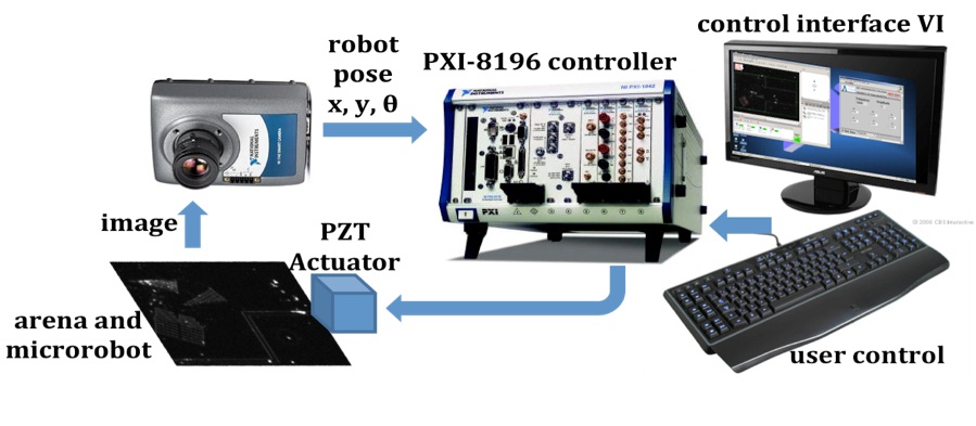
Figure 8 Hardware setup using National Instrumentsdevices microrobot systems
Benefits of using LabVIEW and NI toolsin our project
LabVIEW and NI tools were beneficial throughout this project; the ease with which different hardware is integrated and interfaced provides modular, reconfigurable and reliable instrumentation. LabVIEW being a graphical programming environment with modules enriched with variety of functions, sleek interfaces, and reconfiguration capability of hardware/software made this project manageable.
Interfacing
A key benefit of LabVIEW is the ease with which different pieces of hardware interface with the system. User interfaces and graphical representations provide effortless software interfacing to communicate with hardware devices very easily. For example, image acquisition from the SMART camera has been greatly simplified and efficient thanks to high speed Ethernet. Also, Shared Variable concept between real time targets made the integration seamless.
- Parallelism
Compared to most text-based programming where the structure of the source code completely defines the sequence of instruction execution; LabVIEW’s parallel data flow model increases efficiency and simplifies programming. In our project we made use of this feature to log the results of our test and simultaneously generate the actuation signal.
- Hardware Capability
NIPXI hardware allows us to integrate multiple functionality in a single platform to perform advanced tasks such as signal acquisition, processing, and generation; and data communication. FPGA RIO gives flexibility to change our hardware configuration anytime and even offers parallel execution.
- Real Time
Real time hardware from NI gives reliable performance with precise timing, FPGA and real time target like SMART camera gives highly accurate mesurement results and can support microrobotics research great extent.
- CAD Tools Portability
Prominent feature of 3D picture control module in LabVIEW 8.0 later version is to import CAD model and create 3D visualization and also control of a parts. It gives an advantage of animating the process well before implementing it, which subsequently saves time, resources and budget.
Future Work
In future we aim to make use of neural network and intelligent control tools available in LabVIEW to advance our research in microrobotics, we envision its use can make significant difference in terms of automating a process.
Screenshots
Manual Joystick Control
In order to test robot behavior without having a closed loop control, with help of manual joystick control, user defined frequency and amplitude combination can be configured very easily in LabVIEW. Interfaces can be easily customized in appearance and function based on keyboard preference. Conventionally keys W, A, S, and D are used for up, left, down and right motion respectively. In interface shown in Figure 9. Six keys are used; Q and E are two additional frequency options which are close to the basic four frequencies robot responds to.

Figure 9 Manual Joystick Control
Frequency Sweep Test
Figure10 is our test interface for testing purpose, as frequency of a square wave which resonates the leg of a robot is decisive parameter and it varies withr obot design, shape and material. This test setup was designed to sweep for a particular bandwidth with step size that can be varied by a user. For each frequency X, Y and Theta velocity is calculated and logged when it is greater than some significant value.
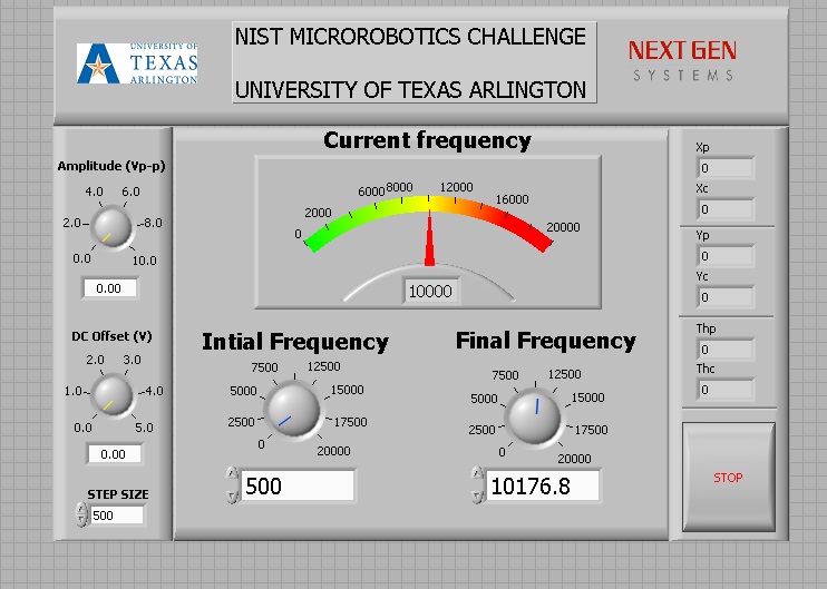
Figure 10 Frequency Sweep Test
Link to Video at http://www.youtube.com/watch?v=GZMUZ1aeLD8
Thank You
UTA Microrobotics team.
Thanks & Regards,
Kunal Raithatha.
CTD - CLAD (I wish I can take off that A, and maybe use it later to replace D 🙂
Easy Tip :- "To copy an image to a VI icon, drag the image file and place it on the icon
located in the upper right corner of the front panel or block diagram" ...If you know any
more reply back.
-------------------------------------------------------------------------------------------------------------------------------
- Mark as Read
- Mark as New
- Bookmark
- Permalink
- Report to a Moderator
Hello there,
Thank you so much for your project submission into the NI LabVIEW Student Design Competition. It's great to see your enthusiasm for NI LabVIEW! Make sure you share your project URL with your peers and faculty so you can collect votes for your project and win. Collecting the most "likes" gives you the opportunity to win cash prizes for your project submission. If you or your friends have any questions about how to go about "voting" for your project, tell them to read this brief document (https://forums.ni.com/t5/Student-Projects/How-to-Vote-for-LabVIEW-Student-Design-Projects-doc/ta-p/3...). You have until July 15, 2011 to collect votes!
I'm curious to know, what's your favorite part about using LabVIEW and how did you hear about the competition? Great work!!
Good Luck, Liz in Austin, TX.
- Mark as Read
- Mark as New
- Bookmark
- Permalink
- Report to a Moderator
Thank you. Smart Camera and Vision Assistant are my favorites. There are still many things I haven't explored about them.
