- Document History
- Subscribe to RSS Feed
- Mark as New
- Mark as Read
- Bookmark
- Subscribe
- Printer Friendly Page
- Report to a Moderator
- Subscribe to RSS Feed
- Mark as New
- Mark as Read
- Bookmark
- Subscribe
- Printer Friendly Page
- Report to a Moderator
Pitch Control Game
Overview:
This tutorial demonstrates the theory and operation of a microphone amplifier. The microphone signal is used with the myDAQ or ELVIS II series in a LabVIEW application called ‘myPitch’ that tests your ability to sing with the proper pitch.
Purpose:
Demonstrate principles of microphone preamplifiers and acquiring audio signals through the myDAQ or ELVIS II series. Audio processing techniques are also shown in LabVIEW.
Background:
Electret microphones are very popular due to their decent performance and low price. The simplest way to imagine the microphone’s operation is to view it as a resistor whose value varies when a sound wave hits it. If a bias current flows through this varying resistance, it will create a small voltage that must be amplified for useable purposes. Click here for a detailed look at sound and vibration.
Equipment:
- NI myDAQ or NI ELVIS II
- NI LabVIEW
- Wire
- Protoboard
- Resistors: 1 kΩ x 2, 10 kΩ, 100 kΩ
- Capacitors: 10 µF
- TL081 amplifier or equivalent
- Electret microphone
Set Up Hardware:
Wiring Instructions
Wire the components to the myDAQ as shown below. If the ELVIS II is being used, all of the same ports can be used.
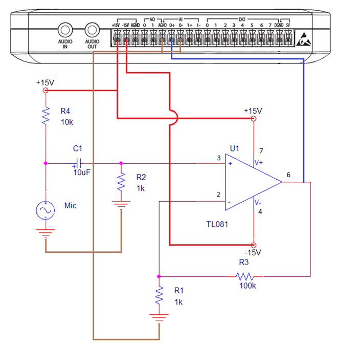
Figure 1: NI myDAQ Wiring Diagram
*Note: Larger wires represent those connected directly to the myDAQ. Red wires are directly attached to a power source, brown wires are directly attached to ground, and blue wires are directly attached to neither.
Circuit Description
In the above circuit, R4 provides the bias current for the microphone. Capacitor C1 prevents the DC voltage across the microphone from being amplified, while allowing the AC signal to pass to the amplifier. Resistor R2 provides a DC bias current path for the TL081 but also creates a high-pass filter with C1, whose cut off frequency can be determined as:

The TL081, R1 and R3 form the non-inverting amplifier whose gain can be described with the equation:

Testing the Circuit
Multisim was used to verify the performance of the circuit using the AC Analysis feature.
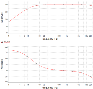
Figure 2: AC Analysis of Microphone Circuit
The simulation shows that the circuit has a gain of 40 dB as predicted and its low frequency roll-off occurs around 15.9 Hz. The upper frequency roll-off is created by the bandwidth of the opamp itself. For small signals, the easiest method to predict the bandwidth of the amplifier is to use the gain/bandwidth product (GBW) specified by the manufacturer. The TL081 has a GBW of 3 MHZ. By dividing this number by our gain of 101, we can predict the 30 kHz bandwidth of the amplifier seen in the simulation.
The Bode application included with the myDAQ can be used to verify the operation of the circuit once it’s built. Be sure to install the capacitor with polarity in the correct orientation, and use care when inserting the microphone into the breadboard.
To test the circuit with the bode analyzer, wire analog input 1 [AI 1+] to pin 6 of the op-amp. Wire analog input 0 [AI 0+] and analog output [AO 0 ] to the positive terminal of the 10 µF capacitor. Connect AGND to the negative input terminals [AI 0-] and [AI 1-].
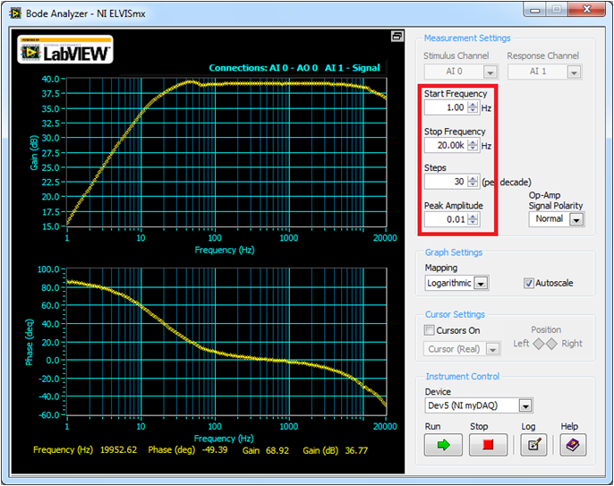
Figure 3: Bode Plot of Microphone Circuit
Software Instructions:
LabVIEW User Interface
Once the signal is picked up by the microphone, we will use it in a LabVIEW application called 'myPitch' that will test your ability to hold the proper pitch. The user interface we created allows the user to choose a song and difficulty, and then run the program and attempt to maintain their voice at the same pitch as the song.
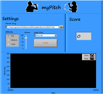
Figure 4: 'myPitch.vi' Front Panel
Coding Strategy
The basic coding strategy for our program is shown below. For a more detailed description, check out the block diagram of ‘myPitch.vi.’
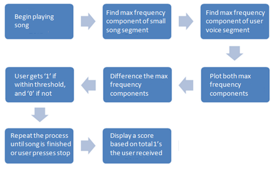
Figure 5: Coding Diagram
How It Works:
Once the microphone is set up and the LabVIEW program is open, we’re ready to play myPitch. Follow the instructions below for a detailed explanation of how to play:
- Plug your myDAQ or ELVIS II into the computer.
- Plug headphones into the computer headphone jack.
- Open myPitch.vi.
- Set the controls in the ‘Settings’ box.
- Pick whatever song you’d like to sing (must be .wav format).
- Set the difficulty.
- Adjust the volume.
- Choose the proper device.
- Click Run.
- Sing into the microphone, trying to keep the pitch of your voice as close to the song vocals as possible (song comes from headphones).
- Continue singing until the song ends, or press Stop to end the song early
- The program will end, and a score representing the percentage of notes in the proper range will be displayed.
Tips and Tricks:
- It may be beneficial to test the system with a single pitch to ensure proper functionality.
- The pitch with which the user is judged is based on the loudest frequency component in each song segment. This pitch could come from either instruments or vocals, so there may be significant differences from the pitch of the vocals of the song and the pitch used to judge the user, depending on the characteristics of the particular song.
- The filters used in the program are bandpass with a range of 80-1100 Hz, because this is the typical range of the human voice.
- Many aspects of the program, such as difficulty range settings, chart update settings, and filter characteristics can be updated inside the code if you prefer different settings.
Webcasts, Tutorials, and Other How-To Resources
Learn about Sound and Vibration Measurements
Learn About Relevant Training Options: Data Acquisition and Signal Conditioning
Applications Engineering
National Instruments
