- Document History
- Subscribe to RSS Feed
- Mark as New
- Mark as Read
- Bookmark
- Subscribe
- Printer Friendly Page
- Report to a Moderator
- Subscribe to RSS Feed
- Mark as New
- Mark as Read
- Bookmark
- Subscribe
- Printer Friendly Page
- Report to a Moderator
Packet-based Digital Link
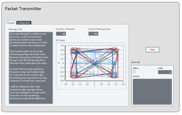
Transmit / receive a text message (converted to bits) over a live RF link between two NI USRPs using a simple packet-based digital protocol.
 |
 |
Packet-based Digital Link using NI LabVIEW Communications System Design Suite 1.0 (or higher)
Hardware Requirements
- 2 NI USRP Platforms
Software Requirements
- Using NI LabVIEW 2010 (or higher)
- NI LabVIEW 2010 (or higher)
- NI Modulation Toolkit for LabVIEW
- NI USRP 1.0 (or higher)
- Using NI LabVIEW Communications System Design Suite 1.0 (or higher)
- NI LabVIEW Communications System Design Suite 1.0 (or higher)
- NI USRP 2922 (or another NI USRP Platform that supports the desired frequency)
Working with the Example
- Unzip all files into a new folder
- The top-level VIs and subVIs are organized in a LabVIEW project file, USRPPacketComm.lvproj. Load this file into LabVIEW.
- In the LabVIEW project explorer, find the entries for two top-level VIs: USRP Packet Receiver.vi and USRP Packet Transmitter.vi. Open these VIs in LabVIEW by double clicking their entries in the Project Explorer.
- The user interfaces (Front Panels) for these VIs use tab controls to organize input / output parameters into logical groups. On USRP Packet Transmitter.vi, click on each of the tabs and confirm correct settings for input parameters:
- Tab: Specify Message: Set the Message text to transmit.
- Tab: Specify Packet: Set the lengths of the bit fields that comprise the packets to transmit
- Tab: Specify Modulation: Set the type of modulation and parameters for a pulse shaping filter
- Tab: Tx Parameters: Set USRP hardware parameters, including the IP address of the USRP that will act as your transmitter. Confirm that this IP address is set to a connected USRP that is powered on. Also confirm that the Tx Parameters are appropriate for the USRP hardware that you are working with.
- Run USRP Packet Transmitter.vi to begin transmitting. The VI will repeatedly transmits the message until you press the Stop button on the front panel. The Symbol Rate [symbols/sec] indicator on USRP Packet Transmitter.viwill display the symbol rate for the transmitted message. This rate is determined by the combination of the settings you specify on the TX IQ Sampling Rate [s/sec] and the Samples / Symbol controls, specifically, the symbol rate is set to (TX IQ Sampling Rate) / (Samples / Symbol).
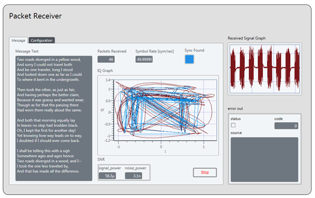
- On USRP Packet Receiver.vi, click on each of the tabs and confirm correct settings for input parameters:
- Tab: Rx Parameters: Set USRP hardware parameters, including the IP address of the USRP that will act as your receiver. Confirm that this IP address is set to a connected USRP that is powered on. Also confirm that the Rx Parameters are appropriate for the USRP hardware that you are working with and that these values correspond to settings made previously for the transmitter.
- Tab: Specify Modulation: Set the type of modulation and parameters for a matching filter. The modulation parameters need to correspond to those set for the transmitter.
- Tab: Specify Packet: Set the lengths of the bit fields that comprise the packets to receive. These should be identical to the values set on the transmitter.
- Tab: Rx Display: See the resulting recovered text message, the live raw / received signal and a constellation graph of one of the recovered packets
Video
- Mark as Read
- Mark as New
- Bookmark
- Permalink
- Report to a Moderator
I have two questions.
I. Why do we need to send the data a second time?
II. Is there a way to see which packet is being sent right now?
- Mark as Read
- Mark as New
- Bookmark
- Permalink
- Report to a Moderator
Excellent examples!
One question: what is the function of sub_NoiseEst_And_Chop_Shell.vi? According to my understanding, this subvi chops the input packets according to the estimated noise power. But what is the advantage to do the chopping? If I removed this subvi from the flow, will there be much different? Thanks!
- Mark as Read
- Mark as New
- Bookmark
- Permalink
- Report to a Moderator
I have two answers:
I. Why do we need to send the data a second time?
A redundant packet is sent to speed up the decode of the entire message--this accounts for edge case packets that are only partially received in a frame. Without the redundant transmission, the receiver would have to wait for the entire sequence to repeat before a chance to acquire the packet again.
II. Is there a way to see which packet is being sent right now?
Kind of--let me explain: The constellation plot on the receiver shows one of the packets that's currently being recovered. Because of buffering, this is likely not the actual currently being transmitted packet. You could modify the transmitter VI to display the current packet frame being pushed to the Tx NI USRP, but again because of buffering it might be a frame or two behind.
- Mark as Read
- Mark as New
- Bookmark
- Permalink
- Report to a Moderator
Another answer to One question: what is the function of sub_NoiseEst_And_Chop_Shell.vi? According to my understanding, this subvi chops the input packets according to the estimated noise power. But what is the advantage to do the chopping? If I removed this subvi from the flow, will there be much different?
The subNoiseEst_And_Chop_Shell.vi crops away portions of the acquired signal that don't exceed a set noise level. What remains (hopefully) are just packets that can be further processed on a packet-by-packet basis. One reason to implement it this way is for efficiency--the subsequent algorithms that handle synchronization don't have to process portions of the signal that we don't think are packets. This speeds up the processing slightly and simplifies how the decoder is reset in that it can be reset between packets directly.
Hope this helps!
- Mark as Read
- Mark as New
- Bookmark
- Permalink
- Report to a Moderator
what is the maximum data rate achievable using the QPSK in this example ??? I mean the PHY throughtput (without county the headers and the periodes where there are no transmissions)
thank you
- Mark as Read
- Mark as New
- Bookmark
- Permalink
- Report to a Moderator
The maximum rate will depend on the speed of your PC and other factors, such as virus scanners running in the background, whether you run the transmitter / receiver on separate PCs, etc. As a point of reference, I've run the example up to 500k symbols/sec on my relatively slow (three year old) laptop, running both Tx / Rx on the laptop. I'm sure much higher rates are possible, given a newer PC, etc.
- Mark as Read
- Mark as New
- Bookmark
- Permalink
- Report to a Moderator
How do I specify the bandwith, for example I use fc = 2,4 Ghz, and a I want the bandwidth to be 86Mhz? As I know in the https://www.ni.com/docs/en-US/bundle/ni-usrp-properties/page/usrppropref/pniusrp_bandwidth.html , there is variable to zhange the bandwidth, but I could not find it in the higher VI (configure signal) .
- Mark as Read
- Mark as New
- Bookmark
- Permalink
- Report to a Moderator
Bandwidth is directly related to your IQ rate. If you set your IQ rate to 10 MS/s, you will get roughly 10 MHz of bandwidth. However, the maximum IQ rate that the USRP supports is 40 MHz and that is receiving 8 bit samples instead of 16 bit samples.
Senior Product Marketing Manager
- Mark as Read
- Mark as New
- Bookmark
- Permalink
- Report to a Moderator
I'm curious about the sub_est_noise_power.vi
I could find bin size, what is that? why it is set to "5"
If I go deeper, why would you compare the size of samples with some number "3000"
And to obtain the energy threshold, why'd you compare with 1e-6?
- Mark as Read
- Mark as New
- Bookmark
- Permalink
- Report to a Moderator
Similar example:NI myDAQ Text Messaging Using Digital ASK Modulation of Audio
- Mark as Read
- Mark as New
- Bookmark
- Permalink
- Report to a Moderator
Dear all,
sometime I receive the error "Memory is full" (https://knowledge.ni.com/KnowledgeArticleDetails?id=kA00Z000000P9mtSAC&l=en-US) when running the Packet Transmitter vi. Specifically the error is associated with the "sub_Text_To_Bitstream.vi".
Do you have any suggestion to correct this issue?
Thank you in advanced
- Mark as Read
- Mark as New
- Bookmark
- Permalink
- Report to a Moderator
Is it possible to run this example using only one USRP?
Dan Franch
Student Space Programs Laboratory
Pennsylvania State University
- Mark as Read
- Mark as New
- Bookmark
- Permalink
- Report to a Moderator
Yes, you can use this example with just a single USRP. There is only about 30dB of attenuation in the front end switch so you may find that it works even without antennas due to leakage in the front end between channels. For this reason we typically recommend 2 units, although 1 unit (2920, 2922, 2930, or 2932) will work. The 2921 is only half duplex and therefore will not work with only the single device.
- Mark as Read
- Mark as New
- Bookmark
- Permalink
- Report to a Moderator
"Memory is full" occurrs when the trigger level is set too high or too low. The energy detector is triggering on noise either near the maximum value or near the noise floor and is causing it to divide the single waveform into thousands of packets rather than the proper number. You can either change the constant on the block diagram of the reciever that sets the threshold, move the antennas around, or change TX/RX gains.
- Mark as Read
- Mark as New
- Bookmark
- Permalink
- Report to a Moderator
I am trying to replace the PN sync seq with my own 256 bit gold sequence that is always BPSK modulated (message bits remain QPSK). I have the transmitter modded successfully, but modifying the recevier is proving to be dificut. I also removed all gruard and padding bits. I can't get constant sync. Also my desired recevier symbol rate vs acutal symbol rate is never the same, but doing some sort of scaling method.
- Mark as Read
- Mark as New
- Bookmark
- Permalink
- Report to a Moderator
Hello, I'm new to LabView so please have pacience with me. I'm doing a practical placement and I have to make a RF transmission between 2 USRP and I found this .vi wich is great, but now I want to send instead of a text message a .wav file, any ideas how can I do that?
Thank you.
- Mark as Read
- Mark as New
- Bookmark
- Permalink
- Report to a Moderator
please could someone explain "sub_est_noise_power.vi" in more details i mean what exactly is the DC , the Noise power estimate and the chopper sub VIs what is the functionality of every one of them
thanks.
- Mark as Read
- Mark as New
- Bookmark
- Permalink
- Report to a Moderator
really awesome example first of all.
i have modified a little bit to your example to serve my purpose that measuring bit error rate.i have add some matlab code in the receiving part to compare the receving data with original data in binary number in order to get the BER.the example works perfectly which i incresed the tx gain and BER drops.but there is one problem which talking about BER we have to find the coesponding signal to noise rato to indicate how it will react. and the SNR that i calculated is from the sub vi noise estimate chop part but when tx gain is increased the ber dropped the SNR dropped too.here doesn't make any sense.or maybe the reading from that part is not real power level of signal and noise??please help me understand better to find the correct way calculate SNR.thanks a lot.
- Mark as Read
- Mark as New
- Bookmark
- Permalink
- Report to a Moderator
can i use one usrp as receiver and the same time run spectral monitoring which is different application from labview?i tried and even used both two rx1 and rx2.but there was some problems.how should i fix that??
- Mark as Read
- Mark as New
- Bookmark
- Permalink
- Report to a Moderator
Thanks for the great example. I tried to modify it for 16 QAM. I got it working for 4 QAM and 8 QAM by switching out all of the PSK stuff for QAM but 16 QAM is failing and I can't figure out why. Then I noticed that 16 PSK on this example is also failing, so there seems to be a problem with the underlying code, or my setup? I suspect the code because the other PSK modulation schems are working for me, just not PSK.
If possible can you please post this example but with working 16QAM?
Also, is 16 PSK from this original example working for you?
Thanks,
Paul
- Mark as Read
- Mark as New
- Bookmark
- Permalink
- Report to a Moderator
Great example. All PSK formats working except 16-PSK. Can any body guide me why 16-PSK is not working? Do I need to make any specific changes to make it run?
Thanks
Joesph
- Mark as Read
- Mark as New
- Bookmark
- Permalink
- Report to a Moderator
Hello Sir
i am using this vi to estimate Signal power and noise power for calculating SNR but i find some issues
when i increase the noise by moving my antenna the SNR also increase instead of decreasing. Can you plz guide about this problum.thanks
- Mark as Read
- Mark as New
- Bookmark
- Permalink
- Report to a Moderator
Lots of things could cause this. RF is a funny thing and that is what makes it so interesting. In your case the only way to do the testing without anomolies is to conduct it in an anacoic chamber and even there you may have funny things happen because of geograpic orientation within the chamber. This is why channel emulators are so popular.
- Mark as Read
- Mark as New
- Bookmark
- Permalink
- Report to a Moderator
Hello everyone
I have the same question above.
Quote from wicak
I'm curious about the sub_est_noise_power.vi
I could find bin size, what is that? why it is set to "5"
If I go deeper, why would you compare the size of samples with some number "3000"
And to obtain the energy threshold, why'd you compare with 1e-6?
Thank you
- Mark as Read
- Mark as New
- Bookmark
- Permalink
- Report to a Moderator
Very intersting example. I am new to Labview and going through some pains to understand the design. I am intersted in transmitting live IP video from webcam feed through USRO link (I have 2 x 2953R units).I have noticed the "sub_text_to_bitstream.vi" under "subGeneratePackets.vi" which is generating a bitstream from the input test. If I am not oversimplifying, I need to find a solution to take IP video imput from Webcam and convert it to bitstream and plug it here.
Will be thankful for any ideas on how to modify this example to achieve this.
Thanks you.
-Zafar
- Mark as Read
- Mark as New
- Bookmark
- Permalink
- Report to a Moderator
Nice example
- Mark as Read
- Mark as New
- Bookmark
- Permalink
- Report to a Moderator
Hi all,
In this case, what is the MT Resample (Complex Clustrer) VI used for? When I remove it, I get the the same result executing the Packet Receiver VI.
I just don't understand since the input and the output sample rate are the same and the initial sample offset is equal to zero.
Thank you,
Bachir
- Mark as Read
- Mark as New
- Bookmark
- Permalink
- Report to a Moderator
When image is converted into packets, how to modify subgenerate packets?
- Mark as Read
- Mark as New
- Bookmark
- Permalink
- Report to a Moderator
Hello everyone
I have the same question above.
Quote from wicak
I'm curious about the sub_est_noise_power.vi
I could find bin size, what is that? why it is set to "5"
If I go deeper, why would you compare the size of samples with some number "3000"
And to obtain the energy threshold, why'd you compare with 1e-6?
Thank you
- Mark as Read
- Mark as New
- Bookmark
- Permalink
- Report to a Moderator
Please email this type of support question to:
support@ni.com
- Mark as Read
- Mark as New
- Bookmark
- Permalink
- Report to a Moderator
The constants in the energy detector were likely chosen based on brute force analysis. Perhaps an adaptive energy detector would be good and could be something someone contributes back to the community.
- Mark as Read
- Mark as New
- Bookmark
- Permalink
- Report to a Moderator
Hello Paul
How did you get it working for 8-QAM? Please can you help?
Thanks,
- Mark as Read
- Mark as New
- Bookmark
- Permalink
- Report to a Moderator
Hello everyone,
How can i modify it for 8-qam? Can you help?PLEASE!
Thanks in advance,
- Mark as Read
- Mark as New
- Bookmark
- Permalink
- Report to a Moderator
Hello
I am using two NI-USRP2900 connected with SMA to SMA cable from TX1 to RX2 of the other device. I also add the 30 db SMA attenuator on after the TX1.
When I started the above example using the LabView communication system design suite the default value are 915M as frequency and IQ rate of 400k. Using this setup the message does not all the packets move to the receiver and some of the packets are corrupted. Only when I increase the IQ rate over 500k I get the entire message but still some of the packets are corrupted. Can someone explain this phenomena?
Regards
Eviatar
- Mark as Read
- Mark as New
- Bookmark
- Permalink
- Report to a Moderator
Hello
I am using two NI-USRP 2901 and the message is not transmitted.
Can anyone could explain me why ?
- Mark as Read
- Mark as New
- Bookmark
- Permalink
- Report to a Moderator
Hi
Did you figured out the reason why it is not transmitting with NI USRP 2900 ?
Thank you in advance.
Best,
Emna.
- Mark as Read
- Mark as New
- Bookmark
- Permalink
- Report to a Moderator
Hello guys,
I'm trying to run this between 2 computers. One works fine but the other sets its actual frequency and IQ sampling rate values directly to 100k. Does anyone knows why is that?
Thanks
- Mark as Read
- Mark as New
- Bookmark
- Permalink
- Report to a Moderator
hello,
In above vi How can I transmit video? Video is already in binary format if I used read from binary fie then how can I generate fragments of video to send to the receiver side.
please give some idea.
- Mark as Read
- Mark as New
- Bookmark
- Permalink
- Report to a Moderator
Hello everyone,
How can i modify it for 16-qam? Can you help?PLEASE!
Thanks in advance,
- Mark as Read
- Mark as New
- Bookmark
- Permalink
- Report to a Moderator
An example of QAM with modified success is sent to me for reference.
Urgent demand
- Mark as Read
- Mark as New
- Bookmark
- Permalink
- Report to a Moderator
Hi, I'm new to LABVIEW, What is the PN seed for? Does the signal I receive have the same seed or is it not necessary? I am trying to receive a signal from a transmitter from a HACKONE-RF.
slds
THANKS
- Mark as Read
- Mark as New
- Bookmark
- Permalink
- Report to a Moderator
Hello everyone,
How can I calculate the power being used by the transmitter in transmitting a message? How can I change that power? Is the transmitter gain the only handle for that? Also, how can I find the error rate in the packet transmission?
I wish to plot Power vs B.E.R. curves for various PSK schemes.
Any help is highly appreciated!
- Mark as Read
- Mark as New
- Bookmark
- Permalink
- Report to a Moderator
Have you found any solution about BER plotting?
- Mark as Read
- Mark as New
- Bookmark
- Permalink
- Report to a Moderator
I am trying to calculate BER, transmitted, received power between two USRP-2922 .My BER is either zero or way above 1.How to fix this?
Any help is highly appreciated!
