From 11:00 PM CST Friday, May 9th - 3:00 PM CST Saturday, May 10th, ni.com will undergo system upgrades that may result in temporary service interruption.
We appreciate your patience as we improve our online experience.
From 11:00 PM CST Friday, May 9th - 3:00 PM CST Saturday, May 10th, ni.com will undergo system upgrades that may result in temporary service interruption.
We appreciate your patience as we improve our online experience.
11-03-2011
03:06 PM
- last edited on
04-27-2025
11:39 AM
by
![]() Content Cleaner
Content Cleaner
The new NI SoftMotion Module we just released contains new officially supported IP blocks for power electronics control, including Trapezoidal and Space Vector commutation for three phase PMSM/BLDC motor/generators and inverters, Clarke and Park transforms, special PID control algorithms, etc.. These IP blocks are part of the NI SoftMotion Module 2011 f1 and NI RIO 4.0.1 release.
For those of you working on field oriented, vector control algorithms in particular, I hope that this will be useful. We are keen to hear your feedback and suggestions. I'm excited that we now have power electronics IP as part of an official NI supported product.
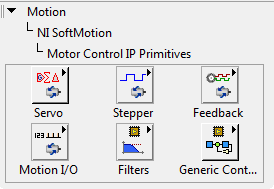
Here are some screenshots of the new palettes. After installing, on the LabVIEW FPGA palette you can find the IP cores under NI SoftMotion > Motor Control IP Primitives > Servo Control > 3-Phase Servo Control.
Subfolders for Servo (PMSM/BLDC), Stepper, Sensor Feedback, Filters, etc.:
Servo (PMSM/BLDC) IP cores for the FPGA. There are new fixed-point PI and PID algorithms with higher precision internal word lengths. The Spline Interpolation algorithm is intended for precision motion control, but it's also useful for a wide range of applications, such as communicating between loops executing at different rates without the stepped signal edges caused by zero-order-hold effects (discrete time sampling that makes the signal look like a stair step to the faster loop, which will cause any derivatives/poles in the faster loop to "explode" numerically-- spline interpolation can be used to smooth the signals resulting in nice stable numerical results).

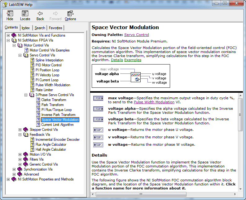
Clarke and Park Transforms, 3-Phase Space Vector Modulation, I2T current/temperature limiter, and a special PI controller for Flux/Torque loops. The Park Transform modifies the two phase orthogonal system (alpha,beta) into the flux,torque (d,q) rotating reference frame. The output is called the current vector. The Clarke Transform modifies the three phase system into the (alpha,beta) two dimensional orthogonal system. The Inverse Park Transform modifies the flux,torque (d,q) rotating reference frame into a two phase orthogonal system (alpha,beta).

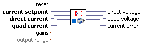
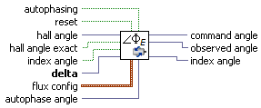
Here's a detail of the flux/torque control loop PI algorithm for use with field-oriented control (FOC) commutation calculations. Direct Current specifies the direct current vector (d) from the Park transform. Quad Current specifies the quad current vector (q) from the Park transform.
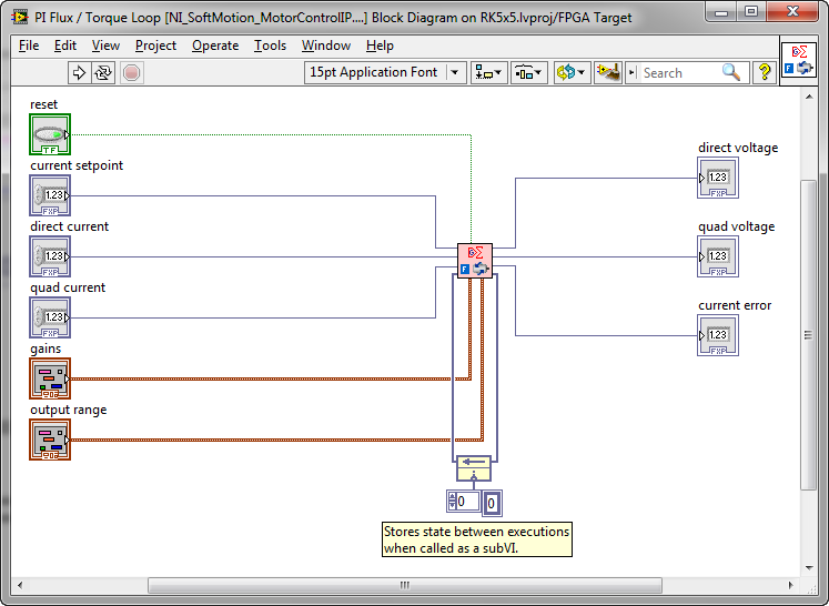
Block diagram showing the fixed point inputs and outputs. A few things I love about the way it's implemented: 1. The state information is stored externally, a development practice that's because it makes it relatively easy to create a multi-channel version of your algorithm, 2. Everything is implemented in native LabVIEW G code, so you can go in and tweak/edit the algorithm freely and easily-- the philosophy of "LabVIEW to the pin" (avoid block boxes), 3. The underlying code is documented, including information about latency time resulting from the chosen pipelining approach.
Sensor feedback VIs. The Flux Angle Calculator calculates the angle of flux for the Park and Inverse Park transforms.
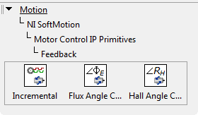
The flux angle calculation is based on the delta output of the Incremental Encoder Decoder or a valid Hall angle. It also support autophasing for brushless DC/PMSM motor control applications.
3-Phase PLL, Matrix*Vector Multiply, and Multichannel PID (implement up to 256 PID loops at 30+ kHz with minimal FPGA resource consumption). If you need a single channel PLL for single-phase power inverters, there is a Costas Loop PLL associated with the LabVIEW FPGA RF Communications Library that works well. It can be downloaded from this thread (PLLTest.zip).

Speaking of multichannel, also check out the multichannel low pass/high pass (Butterworth) and notch filter IP cores-- also very efficient in terms of FPGA resource utilization. These are location on the top level FPGA Math & Analysis palette. One things that's cool is that the filter coefficients are run-time changeable-- you can calculate new filter coefficients on your host processor and send to the FPGA while it's running. This is obviously important if the filters are part of your control loop and therefore need to be tuned. You can use the notch filter, for example, to decrease the gain of your control system at certain resonant frequencies you want to avoid. Obviously, the DC and RMS measurement VI is very important for electrical power applications.
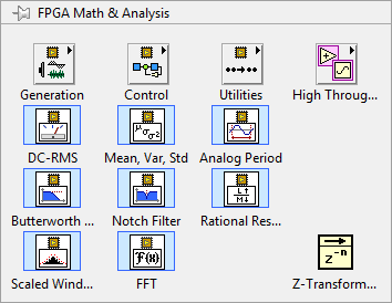
The Analog Period Measurement algorithm above is obvisiously very useful in AC power applications-- for example, you can use it to measure the frequency of an AC signal, or measure the phase difference between two AC signals. Below is the recommended way to use it in electrical power applications. First, clean up the AC signal using a Butterworth Filter. In the configuration page, set it to be a 4th order lowpass filter with a 70 Hz cutoff frequency. With proper filtering, a hysteresis value of around 1 V may be fine. In the configuration page for the Analog Period Measurement function, place a checkmark in the Interpolate crossings checkbox. The Interpolate crossings setting computes the linear interpolation of the crossing instant to 8-bit accuracy. For sinusoidal signals, it can provide a significant increase in accuracy. Following this approach, you can achieve an extremely accurate period measurement.

Do you RTFM?  The main help file to look at is "nimclvfb.chm". Screenshot below. You can access the online version here.
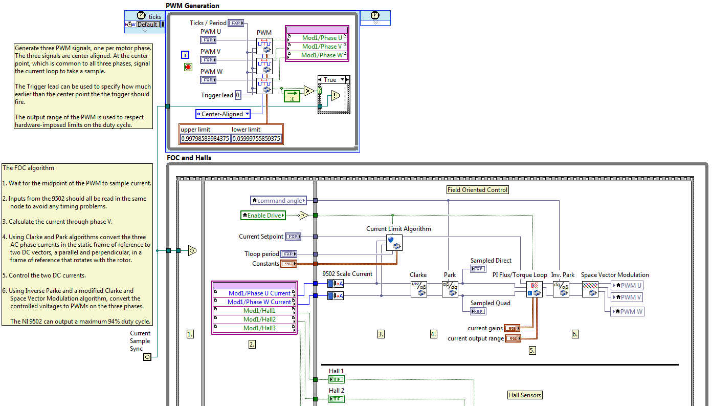
In addition to the IP blocks, there are complete reference design examples for Space Vector (FOC) Position Control, Space Vector (FOC) Velocity Control, and Trapezoidal Commutation. These examples are ready to run using an NI 9502 module and AKM BLDC motor. Here's a screenshot from part of the FPGA VI on the FOC Position Control example.
The beautiful simplicity of the LabVIEW FPGA block diagram is amazing. This is graphical system design. It's like LabVIEW was invented to write power electronics control algorithms for FPGAs.
What do you think? Pretty cool, right? Please share your thoughts, comments and questions.
09-14-2016 09:10 AM
Hi there,
Anybody who would be able to point out the location of the VI, which is illustrated on the last screenshot?
I have the reference design materials, but I had no luck finding the above mentioned VI.
your help is appreciated,
regards,
Alex
09-14-2016
02:57 PM
- last edited on
04-15-2025
05:32 PM
by
![]() Content Cleaner
Content Cleaner
Good question. If you have the NI LabVIEW SoftMotion installed with LabVIEW 2015, you can find the top level project here:
C:\Program Files (x86)\National Instruments\LabVIEW 2015\examples\motion\Primitives\HW\FOC Velocity Control (9502)\Velocity FOC.lvproj
Then you can find the FPGA control application here:
C:\Program Files (x86)\National Instruments\LabVIEW 2015\examples\motion\Primitives\HW\FOC Velocity Control (9502)\Velocity FOC FPGA.vi
I believe this example was depricated in the latest version of NI LabVIEW SoftMotion, so you'll probably want to install the version linked above or this one.
I also have LabVIEW FPGA floating point example code for field oriented control of a squirrel cage AC induction motor (with rotor flux observer) if you are interested.
09-16-2016 06:39 AM
BMac,
I owe you a big thanks for your fast-reply!
As you pointed out - the example I was looking for was depricated. I had to install the 2014 version of SoftMotion module.
For now I just wanted to experiment with a simple BLDC motor with which we were experiencing some interesting problems.
After changing the motor supplier, the motors started to behave in an "non-symmetric" way. Even an official Texas Instruments driver had problems to drive the motor - big difference in CW/CCW directions regarding the RPM and power consumption.... 😕
Anyway, I've just started to refresh my know-how in connection with system control / simulation ... - I would definitely like to take a look at the squirrel cage example code!
thanks BMac,
regards,
Alex
