- Document History
- Subscribe to RSS Feed
- Mark as New
- Mark as Read
- Bookmark
- Subscribe
- Printer Friendly Page
- Report to a Moderator
- Subscribe to RSS Feed
- Mark as New
- Mark as Read
- Bookmark
- Subscribe
- Printer Friendly Page
- Report to a Moderator
- 3D Image Reconstructor
- Loading Pre-defined Model Data
- Loading External Image Files
- Miscellaneous Visualization Features
3D Image Reconstructor
The three-dimensional image reconstruction is to reconstruct a three-dimensional model from a set of two-dimensional image slices. It provides a realistic visualization technique that helps you do analysis and make judgment. This technique is widely used in many areas from medicine to physics and engineering. For example, the MRI scanner produces a set of two-dimensional image slices of tissue. By using image reconstructor, clinicians can view the internal structure in three-dimension, which provides detailed information to region they are interested in.
The iso-surface is one of the common ways to reconstruct image from volume data in three-dimension. The iso-surface is an analog of contour line but in three-dimension. It is a surface constructed by points of constant value, such as pressure, temperature and velocity, within a volume of space.
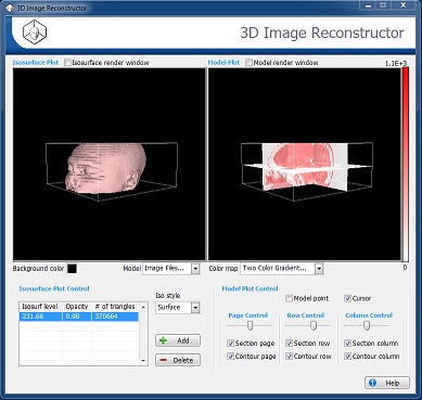
The 3D Image Reconstructor in Biomedical Workbench of LabVIEW Biomedical Toolkit is an application for reconstructing a three-dimensional model by iso-surface way. You can either load the pre-defined model data or external image files from real applications. This application offers miscellaneous ways to visualize both the generated iso-surface and the original two-dimensional image slices.
Loading Pre-defined Model Data
Complete the following steps to load the pre-defined model data.
- Launch the 3D Image Reconstructor.
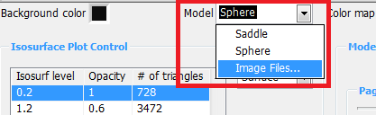
- Click the Model control and select the pre-defined model from Saddle, and Sphere.
Loading External Image Files
Complete the following steps to load the external image files.
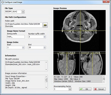
- Click the Model pull-down menu and select Image Files to display the Configure Load Image dialog box.
- Click the File Type pull-down menu to select the type of the external image files. The 3D Image Reconstructor supports the following image file types:
- BMP
- DICOM
- JPEG
- PNG
- Click the Browse button next to the Folder path text box and navigate to the directory that contains image files.
- Specify the prefix of the image files in String prefix. For example, if the image files are named as MYPIC_001.bmp and MYPIC_002.bmp, enter MYPIC_ in String prefix.
- Specify the width of number of the image files in Number suffix width. For example, if the image files are named as MYPIC_001.bmp, MYPIC_002.bmp, enter 3 in Number suffix width.
- In the Image Index section, specify the start and end indexes of the series of image files that you want to load.
- Review the file path information and image information in the Information section.
- In the Configure Load Image configuration dialog box, enter the number of image files you want to load in the Count control.
- In the Configure Load Image configuration dialog box, enter the factor to resize the image files in the Downsampling Factor control. If the original image size is m-by-n, the 3D Image Reconstructor resizes the images to m/factor-by-n/factor.
Note The 3D Image Reconstructor costs more CPU and memory footprint to reconstruct a three-dimensional model for image files with larger size. - Click the OK button to load specified image files and to close the Configure Load Image dialog box.
This screenshot is using the sample data from Taylor S. Amarel (http://decibel.ni.com/content/message/18240#18240😞
Miscellaneous Visualization Features
- Launch the 3D Image Reconstructor.
- Load the pre-defined model data or external image files.
- The 3D Image Reconstructor provides the following visualization features:
- Click the Colormap control and select different color map setting that applies to both the Isosurface Plot and Model Plot.
- Drag mouse in either the Isosurface render window or the Model render window to change the position of camera for both the Isosurface Plot and Model Plot.
- Use the Zoom control in the Camera section to zoom in or out both the Isosurface Plot and Model Plot.
- Place a checkmark in the Model Point checkbox in the Model Plot page to show the model point in the Model Plot.
- Place a checkmark in the Contour checkbox in the Model Plot page to show the contour lines at specified volume level on the section of page, row and column in the Model Plot
- Click the Add button in the Isosurface Plot Control section to add an isosurface. The Add Isosurf Level dialog box appears.
- Use the Isosurf Level control to specify the volume level at which the 3D Image Reconstructor generates the isosurface.
- Click the OK button to add the isosurface.
- (Optional) Double-click an isosurface level in the Iso table to update the isosurface level by using the Update Isosurf Level dialog box.
See the following as an example – (the same data from Taylor S. Amarelhttp://decibel.ni.com/content/message/18240#18240)
- Mark as Read
- Mark as New
- Bookmark
- Permalink
- Report to a Moderator
The Iso value specifies the volume level at which this VI generates the isosurface and isonormal.
Let say: For an 8-bit image the Isovalue was 100 for example. All pixels with a gray value greater than 100 will be reconstructed into a 3D image. Right?
For the medical field, it is interesting to reconstruct certain gray value ranges, for example the range between 50 and 150!
Is it possible to modify the "Isosurface Extractor VI".
I'm looking forward to hear from you. Thanks in advance
Pete
- Mark as Read
- Mark as New
- Bookmark
- Permalink
- Report to a Moderator
I agree. The ability to adjust the min and max values to hilite a range of values is critical.
Also, can someone tell me where the control / menu item is that allows one to load external images?
Don
- Mark as Read
- Mark as New
- Bookmark
- Permalink
- Report to a Moderator
I have one question about the 3 D reconstruction algorithm of the BMT 3D Image Reconstructor!
I have a DICOM CT image serie with about 200 axial images (dimension: 512x512 pixel, slice thickness: 0,6 mm).
If I try to use the 3D Image Reconstructor from the BMT, its took a very long time to load the images and then it runs into an "not enough memory" error. So its not possible to reconstruct a 3D model from these images.
Yesterday I have tried an open source software for medical image reconstruction. The same 200 images were loaded very fast. Also the reconstruction of the 3D model and the presentation of the saggital and coronar views is very fast (some seconds) without any memory problems. The 3D model is really impressive and could also presented in different color palettes (like the palettes in Imaq-Vision). You can rotate and also crop the 3D modell!
This open source software is called "3Dim Viever" http://www.3dim-laboratory.cz/software/3dimviewer/
Do you have an idea why this software could load and reconstruct 200 images so fast without any memory problems? Is there a possibility to use the "3Dim Viewer" libraries in LabVIEW and/or BMT?
Thanks in advance
Piet
