- Document History
- Subscribe to RSS Feed
- Mark as New
- Mark as Read
- Bookmark
- Subscribe
- Printer Friendly Page
- Report to a Moderator
- Subscribe to RSS Feed
- Mark as New
- Mark as Read
- Bookmark
- Subscribe
- Printer Friendly Page
- Report to a Moderator
NI VeriStand Add-on: NI 272x Resistive Simulation
NI VeriStand Add-on: NI 272x Resistive Simulation
Overview
The custom device attached integrates the NI 272x series resistive simulation hardware into NI VeriStand.Instructions for Use
| 1. Add the NI 272x Resistive Simulation Custom Device to the System Definition. When added a new device, a configuration dialog will be shown. You can choose a predefined 272x card or a custom channel configuration. In this dialog you also can also set the mode, default value and RTD simulation settings for each hardware channel. You can also select if you would like to create NI VeriStand channels for hardware resistor bank to bank connections. | 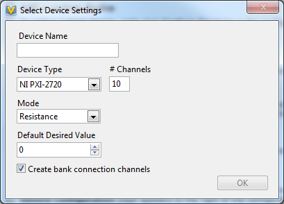 |
| 2. Configure the device name and update rate on the main page. | 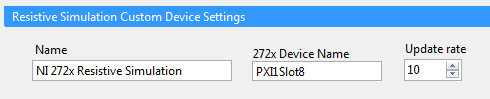 |
|
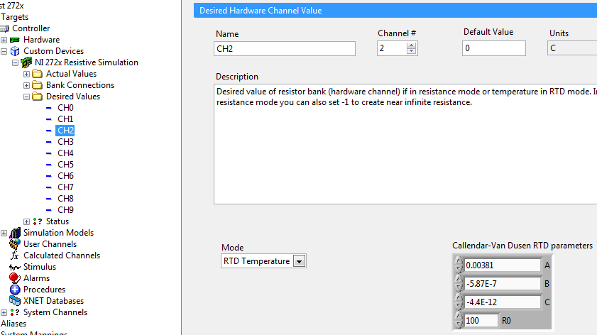
3. If needed, set the simulation mode for individual channels by expanding the "Desired Values" section and selecting a channel:
|
 |
Installing the NI 272x Resistive Simulation Add-On
- Download the attached device.
- Follow the instructions provided in Readme.rtf
Requirements to Run the NI 272x Resistive Simulation Add-on
Software
- NI VeriStand 2011 or later
- Daqmx 9.5 or greater
Hardware
- NI 272x series hardware
Add-on Requirements to Modify the NI 272x Series Custom Device
Software
- NI Daqmx 9.5 or greater
- NI 272x Reference VIs
Known Issues
- Fixed in 2.1.0 This custom device can use significant amounts of memory: about 15 MB per instance. More than 256 MB of system memory is recommended.
- Providing a desired value outside of the possible hardware range of simulation will cause error -363506 and the device will shut down.
Version History
2.1.0
- <Feature> Performance improvements and reduced memory usage
- <Feature> More error handling
- <Feature> Added French, German and Japanese error messages. See updated install instructions
- Now built against NI-272x Reference VIs version 13.0
2.0.2
- <Bug> Resolved an issue causing the device to continue simulating a resistance even after the system definition was undeployed from the target. Now, the resistance will go to infinity.
2.0.1
- <Bug> Resolved a critical issue causing a pop-up window to appear repeatedly when running the device on windows.
2.0.0
- <Bug> Fixed issue that actual value's reported by the custom device were only accurate for one iteration. After the first iteration, they were changing to the desired value
- <Change> Cleaned up the source code
- <Change> Hardware Device name now must be specified when adding custom device to system definition file
- <Change> Rearranged the source code project and library hierarchy
- <Feature> Reduced the size of the built custom device configuration LLB from 5 MB to less than 1 MB.
- <Feature> Improved performance
- <Change> Cleaned up the file structure of the download
- <Change> Renamed the custom device to NI 272x Resistive Simulation
- <Change> Relocated the device in the right click menu to be behind the National Instruments menu
- <Bug> Device will no longer print to console every time a value is changed
- <Bug> Desired value page will now display the correct RTD simulation parameters after changing them, clicking to a different page, and clicking back to the desired value page
- <Feature> Page for desired hardware channel value now allows configuring default value and displays its units
- <Feature> Page for actual hardware channel value now displays the hardware channel # it corresponds to and its units
- <Bug> "Desired value" channel default value's are now applied to the hardware resistance simulation when the system definition is deployed (on the first iteration of this custom device)
- <Bug> "Actual value" channels now have a default value of +Inf as the hardware resistance simulation is not connected to the PXI front panel connector until the first set of a desired value (which happens on the first iteration of this custom device)
- <Bug> Hardware will no longer connect the simulated resistance values to the PXI front panel connector until the first resistance value is set
- <Bug> Hardware will now only connect the resistance channels you are controlling to the front panel connector, rather than all of them (if you deleted some of the channels in NIVS)
- <Bug> Hardware will now revert to infinite resistance (disconnected resistance terminals) when system definition is undeployed
- <Change> New status section replaces the "system" section. This status section reports timing and error information. The old loop rate channel is now a setting configured on the main page
- <Change> Channel names no longer repeat their parent section names. For example "Desired Values/Desired value 5" is now "Desired Values/CH5"
- <Feature> Actual value and desired value channels now have units (Ohms or Celsius or custom)
- <Change> Bank connection section renamed "Bank Connections" and channels inside renamed to "CH# to CH#"
- <Bug> Fixed a bug causing custom device channels to be created all in resistance mode even if you specified temperature mode on the configuration dialog
- <Change> Removed extra blue heading bars from half way up pages
- <Bug> Fixed a bug that prevented the desired value channel from automatically renaming if you change the hardware channel #.
- <Feature> Actual value channels will now rename themselves and change their units if you change the corresponding settings of the desired value channel. if you had not already changed their name to something custom
- <Bug> Fixed a bug that allowed deletion of entire sections of the custom device tree, which would result in run time errors
- <Change> Removed the drop down list for device name since it was defaulting to an invalid device name and didn't work for RT targets. Now you must type in the name to a text box, similar to DAQ devices
- <Change> Default update rate is now 10 Hz instead of 1 Hz
- <Bug> Dialog for configuring the device after adding it to the system definition is now centered on the screen
- <Feature> Creation of bank creation channels is now optional
- <Feature> You can now change the hardware banks that a bank connection channel applies to and the channel will be renamed automatically. For example "Bank Connections\CH0 to CH1" could be changed to channel 5 and it would rename to "CH5 to CH6" if you had not already changed their name to something custom
- <Feature> New delete multiple items right click option available to quickly remove multiple channels from the system definition
- <Change> Right click item and button on main page "Remake Channels" removed.
- <Feature> New right click and button options on each section "Actual Values" "Desired Values" and "Bank Connections" to add a new channel
- <Change> Changed the default coefficients for RTD simulation to be more realistic and not cause deployment errors
- <Feature> Default desired value selection is now available when adding the custom device
- <Feature> Detailed error information is printed to console in case of an error and included in a text file with the device
- <Feature> Added a detailed rich text readme
- <Feature> Mutation framework added for future custom device revisions so versions after 2.0.0 don't require deleting and re-adding device's to system definitions
1.1.1
- Fixed windows bug in XML. Added Error channel, put in addtional console logging functionality.
1.1
- Fixed default guid in XML. This could cause problems when using multiple custom devices.
Support and Contact
This add-on is provided as open-source software. If it does not meet your exact specification, you are encouraged to modify the source code to meet your needs. It is not officially supported by National Instruments.
If you encounter a problem with this add-on, or if you have suggestions for a future revision, please post to the NI 272x Custom Device Forum. You must use this feedback forum for support. Do not call National Instruments for support for this add-on.
National Instruments does not support this code or guarantee its quality in any way. THIS EXAMPLE PROGRAM IS PROVIDED "AS IS" WITHOUT WARRANTY OF ANY KIND AND SUBJECT TO CERTAIN RESTRICTIONS AS MORE SPECIFICALLY SET FORTH IN NI.COM'S TERMS OF USE (http://ni.com/legal/termsofuse/unitedstates/us/).
Engineer
INTP
- Mark as Read
- Mark as New
- Bookmark
- Permalink
- Report to a Moderator
hello,
In the NI _272x_ResistiveSimulation_v2.1.0_Source_2011.zip, there are some typedef not include. Infact, we need to install NI 272x reference VIs
- Mark as Read
- Mark as New
- Bookmark
- Permalink
- Report to a Moderator
We should probably take the source here down - the latest version is available not on the VeriStand GitHub page. You are right about the dependency that isn't mentioned here. That's part of why we moved the code to github - for an improved developer experience. The dependencies are listed there on the ReadMe that is parsed into the web page.
For future reference (and easier tracking) support and other issues should be directed to the support thread linked above.
Thanks!
Andrew
- Mark as Read
- Mark as New
- Bookmark
- Permalink
- Report to a Moderator
Hello,
if you go out of the positive or negative range or if just type -1 (as reported in the user manual..) the complete simulation will stop.
Can we expect a fix for this Known Issue soon or are we forced to implent our version of the custom device?
Thank you
Davide
- Mark as Read
- Mark as New
- Bookmark
- Permalink
- Report to a Moderator
Hello, Davide_Galli,
It looks like this is Known Issue #2 above. To fix this, the easiest way would be to clear the error and continue running. However, that would only work if the error does not stop the DAQ task. I don't know if that's the case.
The other way we could do this is to coerce the value before we write it.
I won't be able to make this change soon, but we should be able to make it. What time frame are you looking to have this by? You can send me a private message if you don't want those details on this thread.
For future reference (and easier tracking) support and other issues should be directed to the support thread linked above.
Thanks,
Andrew
- Mark as Read
- Mark as New
- Bookmark
- Permalink
- Report to a Moderator
Hello,
Could you sport a built by LabVIEW 2016? Because when I built it, there always is an error.
Sincerely,
Nan
- Mark as Read
- Mark as New
- Bookmark
- Permalink
- Report to a Moderator
do we have the latest version to work compatible with VeriStand 2017?
- Mark as Read
- Mark as New
- Bookmark
- Permalink
- Report to a Moderator
Please provide the latest version to work compatible with VeriStand 2017
