From Friday, April 19th (11:00 PM CDT) through Saturday, April 20th (2:00 PM CDT), 2024, ni.com will undergo system upgrades that may result in temporary service interruption.
We appreciate your patience as we improve our online experience.
From Friday, April 19th (11:00 PM CDT) through Saturday, April 20th (2:00 PM CDT), 2024, ni.com will undergo system upgrades that may result in temporary service interruption.
We appreciate your patience as we improve our online experience.
University: Cardiff University
Team Members: Nicholas Clark (Graduating 2014)
Faculty Advisers: Mr Steve Watts
Email Address: clarknick1990@gmail.com
Submission Language English
Title: RF power amplifier characterisation and its response and limitations within a communications system using the NI USRP platform.
Project entry for the 2013 Student Design Competition
Description:
Using the USRP alongside LabVIEW to build an automated RF amplifier test system to help students experience and understand a modern communications system. Demonstrating key engineering trade-offs and bridging the gap between the analogue and digital components of a communications link.
Products
The Challenge
When studying modern communications systems understanding the role and limitations of the analogue RF power amplifier is of key importance. This component fundamentally affects the communications quality, bandwidth, and power usage. Many of the key design choices, such as modulation scheme, data coding and transmit power will be affected by the amplifier characteristics.
Traditionally, most RF measurements used to characterise and understand the amplifier require the use of expensive equipment. This factor has usually meant that practical RF systems, particularly looking at the amplifier, have been out of the reach of undergraduate and MSc university students - practical work is usually limited to software simulation.
With the advent of the National Instruments Universal Software Radio Peripheral (USRP) an opportunity has presented itself to create a low cost, semi-automated test system which can be used to observe and explore a flexible, software defined, RF communications link.
The Solution
This project uses two USRPs for both an RF source and receiver, connected either side of an RF power amplifier. Central to the system is the LabVIEW development environment which was used to create the complete software test solution.
LabVIEW, as opposed to a procedural text-based language, graphical and dataflow oriented. This feature makes it ideally suited to implementing a communications system where data can clearly been seen flowing from one function block to another. Also, it includes a number of libraries to aid in the implementation of communications systems and specifically their testing. In this project, the modulation and spectral measurements toolkits are extensively used to generate, modulate, demodulate, measure and transform signals. Furthermore, LabVIEW has extensive integration with all National Instruments hardware products further establishing it as it the obvious choice for this project.
Throughout the project it was clear that good software design practise was imperative. It was felt that without it, successfully completion of the project would be difficult and any future work would be severely hindered.
The main application architecture is built around the LabVIEW Actor Framework. This allows for distinct application responsibilities to be encapsulated as separate actors communicating through queued message handlers. Each actor behaves as a process command and scheduler using many utility classes exploiting the features of LV OOP to achieve its functionality.
Below the launcher and receiver user interfaces can be seen. The application allows multiple 'Receivers' to be launched simultaneously to allow for data comparison.
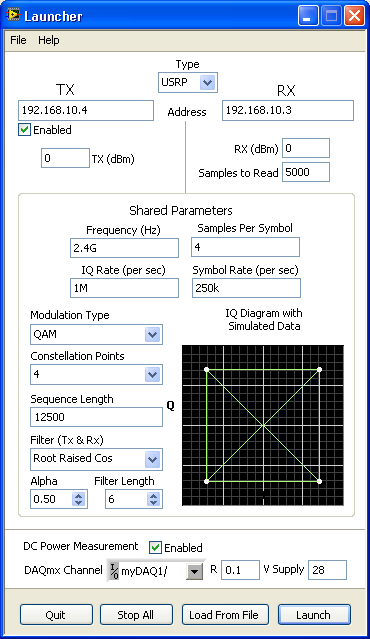
Figure 1 - Application Launcher
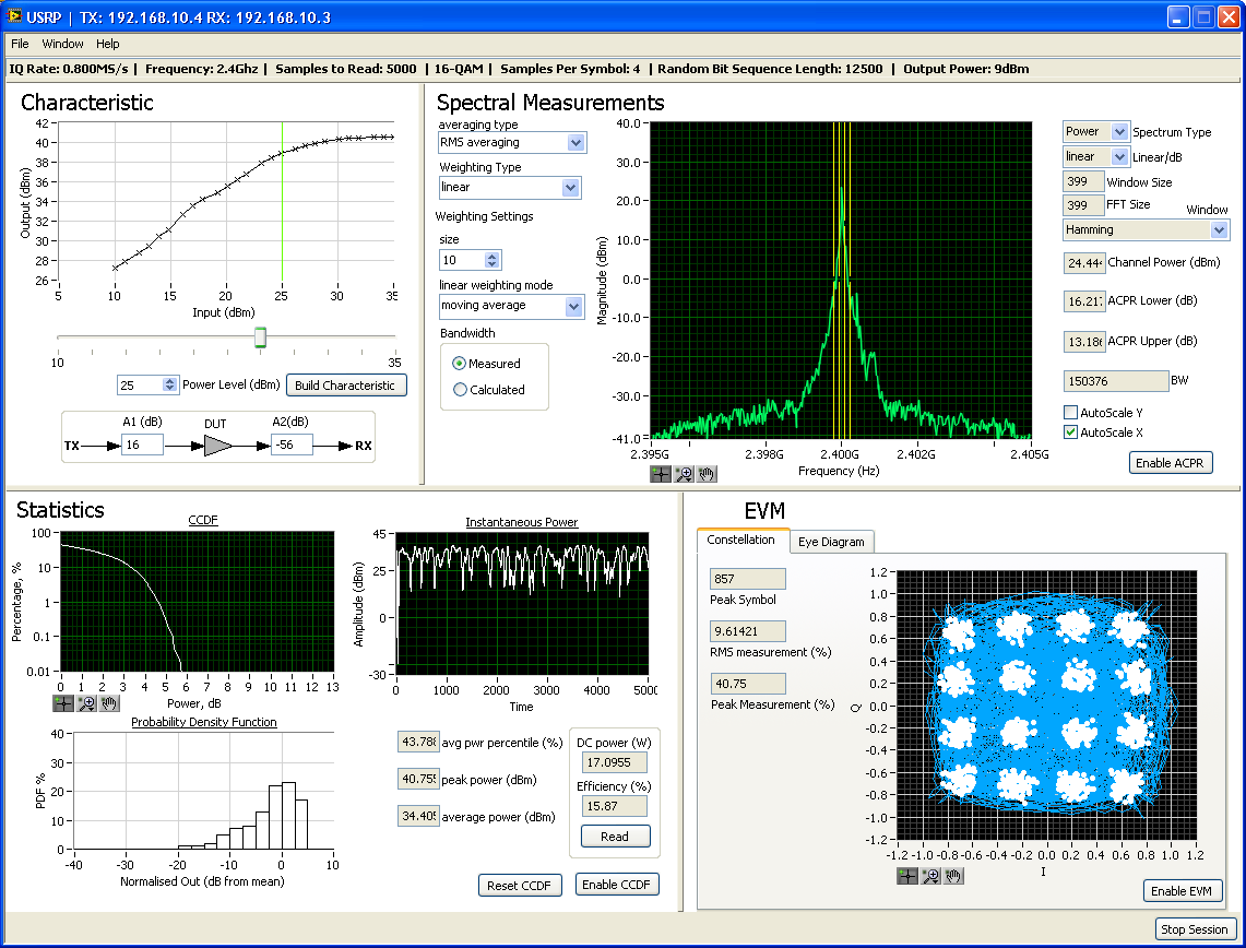
Figure 2 - Main Application Interface
From the receiver, the launcher can be found using ‘Window >> Show Launcher’ and data sets saved and loaded under 'File >> Save/Load’.
A few key VIs snippets can be seen below. When the user 'enables' a measurement, the current state of the enable buttons is captured. Depending on if its required, the application then instructs the transmitter to start or stop transmitting before running the main measurement VI which captures data and performs measurements dependant on the button state. The EVM section has been pictured, similar case structures exist for spectral measurements, efficiency and statistical analysis. Please find attached a high resolution version of the image below.
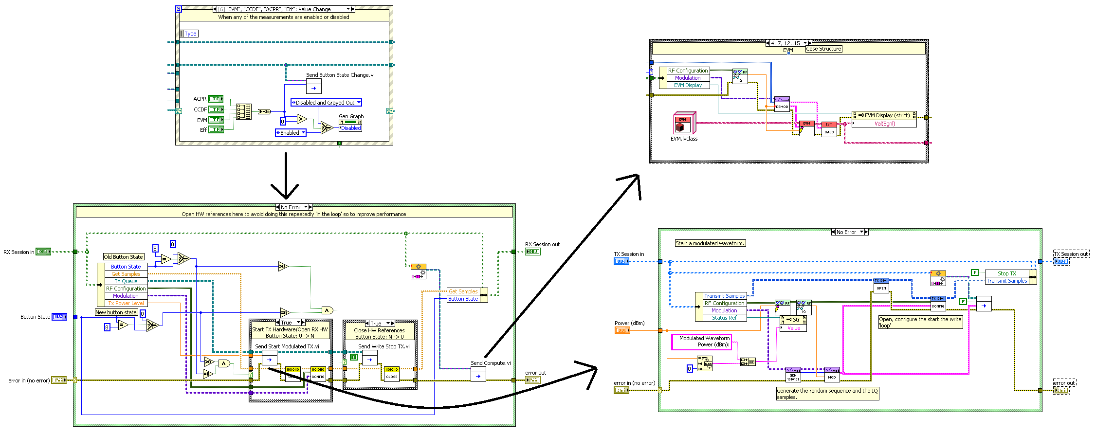
Figure 3 - Key Code Snippets
Key features of the application include:
Power output/input characteristic
Spectrum analyser
Statistical Measurement
EVM & Eye Diagram
Efficiency
Other Software features
Fundamental Power Ouput/Input Characteristic
In this system, the first and most basic measurement is to measure the power characteristic at the fundamental frequency. This plots input power against output power revealing amplifier gain and the point at which compression occurs. This is generated automatically and then the transmitter can be adjusted to operate along this characteristic so that changes in the received waveform and efficiency can be observed.
Efficiency
A key concern of any RF engineer will be the power efficiency of their system. Here, the NI myDAQ has been used to measure the supplied DC Current (and therefore power) so that a measure of efficiency can be calculated. Changing efficiency can be observed by adjusting system parameters such as input power modulation or coding.
Spectral Analysis
An FFT is performed by the spectral measurements toolkit. ACPR is measured so to quantify any spectral regrowth which occurs, mainly as the result of waveform clipping due to amplifier compression.
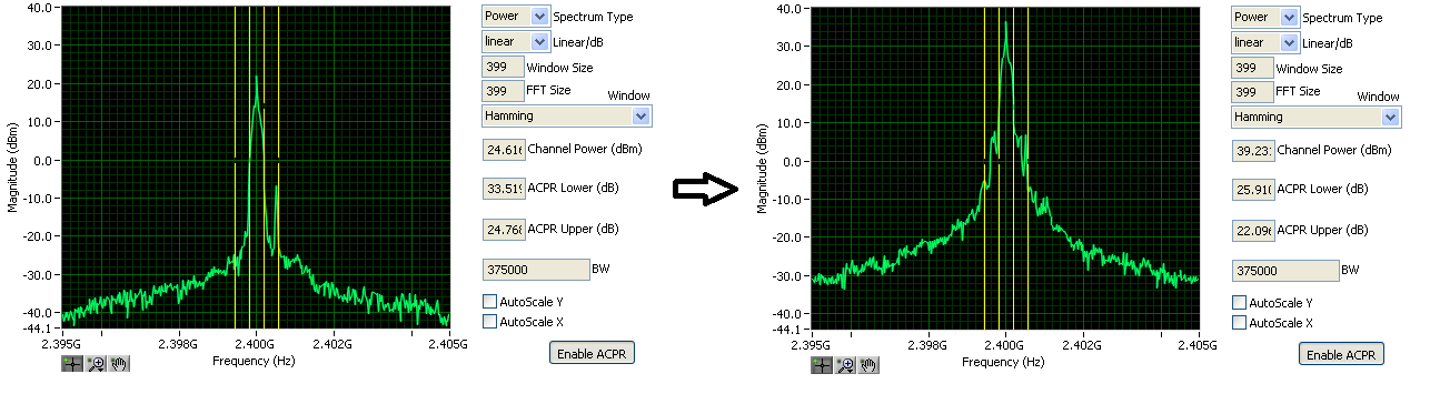
Figure 4 - Spectral content before and after amplifier reaches compression
Statistical Analysis
In a digital RF communications system such as this , the instantaneous power developed by the system is not constant. The output power is rapidly changing as the output signal traverses the constellation. As efficiency and transmission quality changes dramatically as a signal traverses an amplifier's gain characteristic, it is interesting to perform a statistical analysis of a modulated wave to discover how much time a waveform spends at differing power levels. Key observations would be to see if the waveform spends too much time at inefficient low power levels or if the peak power levels push the amplifier too far into compression causing unwanted spectral emissions. CCDF is performed using the modulation toolkit.
Error Vector Magnitude & Eye Diagram
Constellation diagrams, trajectories, eye diagrams and EVM measures are generated by the modulation toolkit. EVM provides a measure of the extent to which a received symbol is ideal and provides an insight into signal quality.
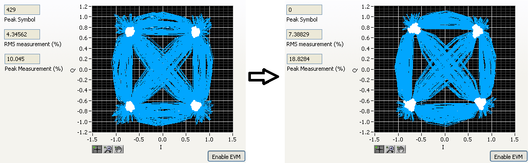
Figure 5 - Deteriorating EVM
Hardware
A system schematic can be seen below; one PC was used connected via Ethernet to the two USRPs. The PA used was a high power device and so required the use of a drive stage to ensure it could be pushed into compression and some attenuation to eliminate the possibility of damaging the USRP. The driver requires a +12V, 2A supply and the Cardiff PA uses 28V, 1A (max) at the drain and a -2V gate. The Cardiff built device is a variable conduction angle amplifier but was primarily used in class A mode. There is scope to add gate voltage control to the software so to allow the system to be characterised across different operating classes. There is also a small fan pictured, this was required because, at best, the device generates 10W RF power with an approximate efficiency of 50%, therefore 10W+ can be generated as heat. Also, pictured is a myDAQ which measures the volate across a small (0.1 Ohm) resistor placed in series with the drain supply. Using this, the supplied current is measured and, as the voltage is fixed, the supplied power.
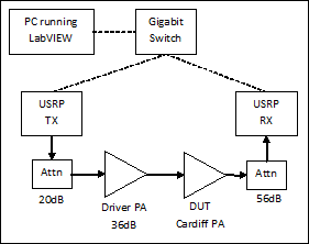
Figure 5 - System Schematic
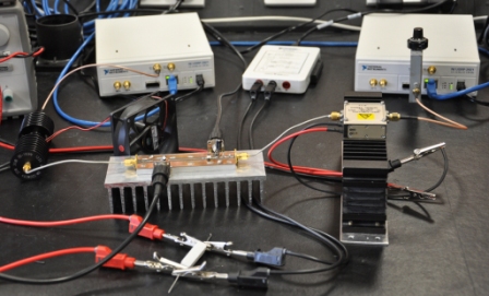
Figure 6 - Physical Setup
This project is presented as a working piece of software with the intention of it being further developed including the writing of a laboratory to be used within an undergraduate setting.
The project was written in LabVIEW 2012 and requires NI USRP, RFSA, RFSG and DAQmx drivers aswell as modulation and spectral measurements toolkits.
It was built between Sept 2012 - March 2013 as my third year individual project forming part of my undergraduate degree in Computer Systems Engineering (MEng)
Below, you can see myself, Nicholas Clark (right) and my supervisor, Steve Watts (left)
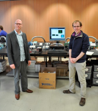 Figure 7 - Project supervisor, Steve Watts & myself, Nicholas Clark
