- Document History
- Subscribe to RSS Feed
- Mark as New
- Mark as Read
- Bookmark
- Subscribe
- Printer Friendly Page
- Report to a Moderator
- Subscribe to RSS Feed
- Mark as New
- Mark as Read
- Bookmark
- Subscribe
- Printer Friendly Page
- Report to a Moderator
Contact Information
University: Cardiff University
Team Members: Lewis Gear graduating 2013
Faculty Advisers: Steve Watts
Email Address: l.gear@hotmail.co.uk
Submission Language: English
Time to build: 6 Months
The development of a bench top UAV design environment and using it to design, build and test a UAV
Description:
The main aim of this project was to develop an autonomous fixed wing model aircraft that would maintain level flight. As a prerequisite, a bench top test facility would be developed that would simulate model aircrafts. It would allow the control systems developed for the UAV to be validated and verified before being tested outdoors.
Products
- NI LabVIEW, NI LabVIEW FPGA Module, LabVIEW Real-Time Module, NI LabVIEW PID and Fuzzy Logic Toolkit
- NI Multisim and Ultiboard
- NI sbRIO 9636
The Challenge
An unmanned aerial vehicle, or UAV, is an aircraft that does not have a human pilot on board. The flight path of a UAV is controlled either autonomously by an on board computer or by a pilot remotely.
UAVs are most commonly known for their role in the military but are becoming more widely used in commercial settings. UAVs offer a number of advantages over manned aircraft such as the ability to enter environments that are dangerous to human life and perform repetitive tasks for long periods of time. They do not need a qualified pilot and can be programmed to complete an entire mission autonomously. These unique capabilities of UAVs have meant that they are currently in use or under consideration around the world for civil and commercial uses such as:
- Wildfire Detection and Management
- Pollution Monitoring
- Event Security
- Traffic Monitoring
- Disaster Relief
- Fisheries Management
- Pipeline Monitoring
- Oil and Gas Security
- Meteorology - Storm Tracking
- Remote Aerial Mapping
- Transmission Line Inspection
Although there are clear advantages of using UAVs, they can often be seen in a negative light because of the possibility of a system malfunction. This project aimed to overcome this shortcoming by developing a bench top test facility where UAVs can be validated and verified before being tested outdoors.
The completion of the test bench would then give way to the main aim of this project; the development of an autonomous fixed wing model aircraft that could maintain level flight. Take-off and landing was to be performed manually, and when instructed by the pilot, the UAV controller was to generate the control surface commands to manoeuvre the aircraft autonomously.
The Solution
Test Bench Overview
The UAV Test Bench was built using LabVIEW combined with FlightGear: a freely available flight simulator capable of modelling small scale aircraft (shown in Figure 1). The Test Bench was used to develop and test the autopilot software used within the UAV Controller. The autopilot was developed for an RC model aircraft within the flight simulator and then deployed to the real UAV without change.

Figure 1. FlightGear
The PID controllers were tuned by stimulating an aircraft and observing the response as seen in Figure 2. The response of the system was then automatically characterised by a number of parameters that are used to approximate a model of the system. Based on this model, a number of methods are used to calculate the PID parameters needed:
- Ziegler-Nichols
- Chien, Hrones, and Reswick
- Cohen-Coon
- Internal Model Control
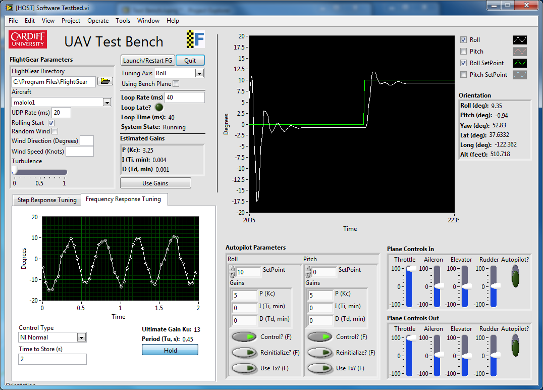 Figure 2. UAV Test Bench UI
UAV System Overview
The software running on the sbRIO 9636 replicated a typical feedback control system as shown in Figure 3. A sensor was in place to measure the Roll and Pitch of the aircraft which would allow the Autopilot to calculate the flap positions that are needed to manoeuvre the aircraft into the desired position.
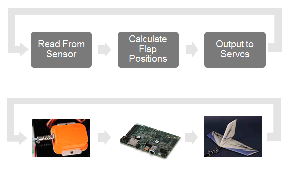
Figure 3. UAV System Overview
MTi-G Orientation Sensor
The xsens MTi-G is an attitude and heading reference system and contains gyroscopes, accelerometers and magnetometers in 3D. The on-board sensor fusion algorithm is able to provide drift-free 3D orientation data accurate to within 0.5 degrees over RS-232 serial. A sponsorship deal was secured with xsens resulting in a free MTi-G. In return, I developed an Instrument Driver so their customers could also use LabVIEW with the MTi-G. It is NI Supported and NI Certified and can be downloaded here and seen in Figure 4.
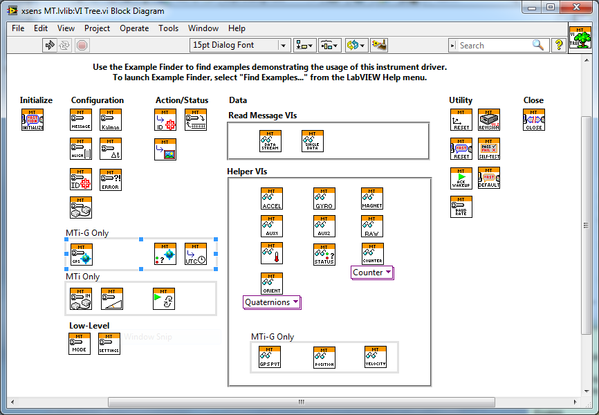 Figure 4. MTi-G Instrument Driver
sbRIO Interface Board using Multium and Ultiboard
While the NI sbRIO 9636 is situated inside the model plane, it must be connected to a number of external devices; the RC servos, RC receiver, radio communication module and orientation sensor. Each of these system components have their own power requirements and have different connectors. A simple of way connecting the external devices to the NI sbRIO was needed so a PCB was made and can be seen in Figure 5 and Figure 6.
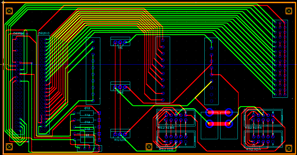
Figure 5. sbRIO Interface Board in Ultiboard

Figure 6. sbRIO Interface Board
sbRIO 9636 UAV Software Overview
The Real-Time OS on the sbRIO 9636 has four loops shown in Figure 7:
- The Sensor Acquisition Loop to read orientation and GPS
- The Data Log Loop logs flight data to an SD card to firstly find the cause of any incidents that may occur and secondly to monitor the response of the autopilot
- The Main Control Loop runs deterministic control using the PID VIs from the NI LabVIEW PID and Fuzzy Logic Toolkit
- The RF Comms Loop to sends data back to the base station so I can monitor the UAV while it flies in real-time
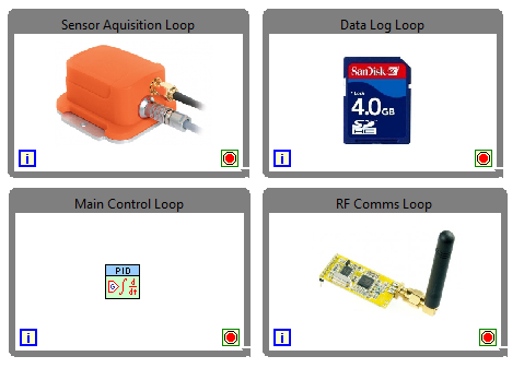 Figure 7. RT Software Overview
The FPGA on the sbRIO 9636 has four main tasks shown in Figure 8:
- Reads PWM commands from the pilot via the RC receiver
- Write PWM signals to all of the servos to change aircrafts attitude (Roll, Pitch, Yaw)
- Read the battery levels to ensure the battery is in a safe state
- Monitor the processes on the Real-Time operating system to ensure they are running safely via the Fail-Safe Controller loop. This loop will make sure that Autopilot is only active if is safe to do so
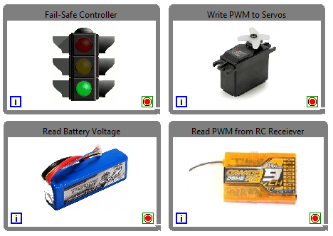 Figure 8. FPGA Software Overview
The Results
The project was successful in producing a UAV Test Bench and an autonomous UAV. The UAV Test Bench was vital to the success of the project and enabled the autopilot to be developed in a simulation environment. The PID tuning techniques allowed the PID parameters to be determined and used on the UAV Controller. Overall, the response of the autopilot seen in the test flights was very similar to that of the Test Bench. A number of test flights were conducted at a local model flying club. The UAV was able to maintain level flight as indented in windy conditions as shown in Figure 10.
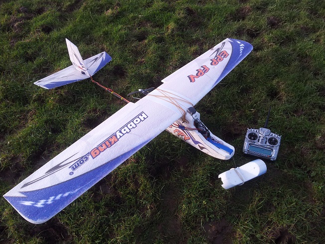 Figure 9. UAV Ready for take-off
 Figure 10. UAV Flying Autonomously
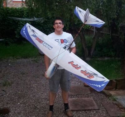 Figure 11. Myself (Lewis Gear) with my UAV
Why National Instruments?
LabVIEW is a very intuitive programming language and it allowed me to create a flexible embedded system that seamlessly integrated with all of my hardware. The ability to have multiple loops running in parallel made it very easy to have parallel processes working together which could have been difficult to implement in other languages.
Since LabVIEW is cross platform, it could run on the Real-Time operating system of the sbRIO and a Windows computer. The ability to develop the Autopilot in the Test Bench and deploy the same code without change to the UAV was essential.
The low power and light weight of NI sbRIO 9636 were crucial for this project. The NI sbRIO could be powered from the onboard 12V batteries and its small form factor meant it could fit inside the relatively small airframe I had.
The nature of this application made it necessary to implement fail-safes to ensure that the UAV operated safely even when elements of the control hardware or software fail. The NI RIO architecture is ideal from this standpoint because most I/O is channelled through the FPGA, which is also the most reliable component of the system. The FPGA was able to monitor the on-board systems and in the event of a problem, revert back to manual mode and give the pilot full control.
The Video
Attachments
Code.zip - The UAV Test Bench and the UAV code. Download and install FlightGear to start developing your own UAV!
Images.zip - The images contained within this document
UAV Poster.pdf - The projects poster
- Mark as Read
- Mark as New
- Bookmark
- Permalink
- Report to a Moderator
Top work Lewis,
Anyone who's tried this sort of thing know's how difficult it is.
Looks like you made great decisions on the tools to use and did a fantastic job integrating everything together. You've acheived a huge amount in 6 months!
- Mark as Read
- Mark as New
- Bookmark
- Permalink
- Report to a Moderator
The code.zip file is a completely different project called Myliedetector. Anyone have a link to
the correct code?
