- Document History
- Subscribe to RSS Feed
- Mark as New
- Mark as Read
- Bookmark
- Subscribe
- Printer Friendly Page
- Report to a Moderator
- Subscribe to RSS Feed
- Mark as New
- Mark as Read
- Bookmark
- Subscribe
- Printer Friendly Page
- Report to a Moderator
NI VeriStand Add-on: Chassis TimeSync Custom Device
NI VeriStand Add-on: Chassis TimeSync Custom Device
NOTE: This addon has been deprecated. There is an officially NI supported version here now: https://github.com/ni/niveristand-synchronization-custom-device
Overview
The Chassis TimeSync Custom Device add-on synchronizes RT system time and PXI chassis clocks. This is accomplished by either reading the PXI chassis clock and setting system time, or by overwriting both system time and the PXI chassis clock when using an external time reference such as the free running clock of a Time-Based Synchronization module, 1588, GPS, PPS, or IRIG-B. This functionality is commonly used for data sampling synchronization and offline data correlation analysis. For more detail and background on these topics, including sample data correlation files see: Time Correlating NI VeriStand Data Logs.
Instructions for General Use
To use the Chassis TimeSync Custom Device, first verify the installation process was followed completely. Some setup is required of your Real-Time target in addition to the custom device so be sure to carefully follow the installation steps that describe this.
|
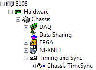
Add the custom device to your system definition under Controller -> Hardware -> Chassis -> Timing and Sync |
|
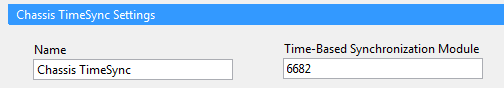
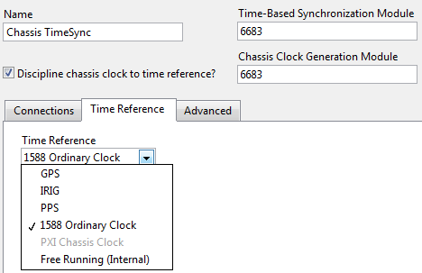
Type in the name of your Time-Based Synchronization Module as defined in Measurement and Automation Explorer (MAX). In a single chassis/controller setup. This is all the setup required. |
|
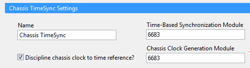
However, if you are using a Time-Based Synchronization Module that supports generating a time disciplined chassis clock (any module other than the 6682 and 6682H), then you should also check the box to discipline the chassis clock to a time reference. These modules offer a much higher precision oscillator than the PXI chassis (1ppm vs 250ppm). You could also select a different, higher precision module like the 6653 or 6674T here, if higher precision (1ppb) is required.
Important Note! When using a PXI Express chassis use a PXI-6683H as the PXI-6683 will not fit in the chassis. Because it is a hybrid module, it cannot drive the chassis clock directly. So if you check the box to discipline the chassis clock to a time reference you must connect the "CLK OUT" on the front of the PXI-6683H to the "CLK 10 IN" on the back of the PXI Express chassis. A simple SMB to BNC cable works well. See pictures in hardware requirements section. Important note: When using a PXI Express chassis the only the Chassis Clock Generation Module PXI-6683H |
|
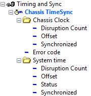
At run time, you can monitor the values of the system time and chassis clock folders to verify synchronization of system time and the chassis clock. |
|
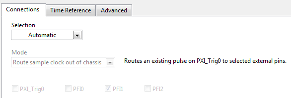
Selecting the main page you can see the custom device has automatically selected to connect any sample clock that is present from single point DAQ or FPGA devices inside the chassis to PFI1 of your Time-Based Synchronization module. This is useful if you have any external single point hardware that needs a sample clock like a MXIe-RIO chassis. If not, you can safely ignore this and the rest of the options and deploy. |
|
If you are also using the Scan Engine and EtherCAT custom device, and additionally have single point FPGA or DAQ hardware in your system, you must select the Chassis TimeSync custom device as your chassis timing master. Do so by selecting the chassis item and changing the chassis master selection. After doing so, you will see the Chassis TimeSync custom device turn bold blue. |
|
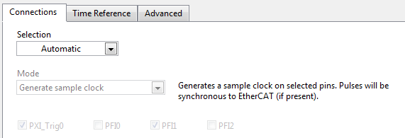
And the main page connections tab will indicate your Time-Based Synchronization Module will generate a sample clock for your DAQ and FPGA devices synchronous with EtherCAT |
|
When using multiple PXI chassis and controllers together, or when using an external time reference is desired, visit the time reference tab and select the external time reference to use. When simply connecting a few PXI chassis and controllers together, the easiest to use is 1588 so they all automatically share time over an Ethernet network. When using 1588, be sure to configure the IP addresses of the Ethernet ports in MAX. |
Instructions for Advanced Use
The connections tab on the main page will either generate a sample clock synchronous with EtherCAT (when present) on PXI_Trig0 and PFI1 or route an existing sample clock out of the chassis from PXI_Trig0 to PFI1 depending on if the Chassis TimeSync custom device has been set as the master device of the chassis. However, if you wish to customize this behavior you can. Change the selection from automatic to custom and manually change the mode as seen below:
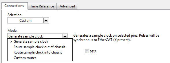
When selected you can pick which pins to use in each mode and have access to two additional modes. Route sample clock into chassis allows picking a PFI pin to route in to PXI_Trig0 if you have an external sample clock you wish to provide to chassis single point devices. For example, from a MXIe-RIO to a DAQ device. You can also select custom routes to type in any source and destination pin to connect. In the custom routes mode a special keyword of "Scan" is available for sources to specify connecting the scan clock to those destinations.
The advanced tab contains two options that can assist in tuning the generated sample clock. These rarely need to be tuned, but are available as seen below:
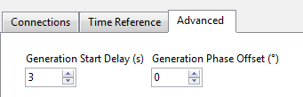
Figure 10
For sample clock generation, this custom device calculates the exact time the first edge occurs so it is synchronous with EtherCAT. This calculation takes time, and when it is finished the calculated start time may have already passed. To prevent this issue, a delay is added to the start time. This keeps the generation synchronous and prevents error. Increase this delay if you're receiving initialization errors regarding the start time.
As previously mentioned the sample clock generated by the Time-Based Synchronization module is synchronous with EtherCAT's scan pulse. However, there is a hardware delay between when the EtherCAT scan pulse happens and the EtherCAT I/O is updated that is variable depending on the number of EtherCAT I/O variables. To compensate for this delay, adjust the phase offset of the generated sample clock.
Installing the Chassis TimeSync Custom Device
- If not already installed, download and install .
- If not already installed, download and install NI-Sync 3.4.0 or later
- Copy the "Chassis TimeSync" directory into your "<Public Documents>\National Instruments\<VeriStand>\Timing and Sync\" directory
- Example destination path on Windows Vista/7: “C:\Users\Public\Documents\National Instruments\NI VeriStand <year>\Timing and Sync”
- Example destination path on Windows XP: “C:\Documents and Settings\All Users\Documents\National Instruments\NI VeriStand <year>\Timing and Sync”
- Using Measurement and Automation Explorer (MAX), install NI TimeSync 1.2 and the TimeSync plugin for NI-Sync hardware to your Real-Time target
- Open MAX
- Expand remote systems
- Select and expand your target
- Right click software and select add/remove software
- Select to install "NI-Sync", "NI-TimeSync", and "NI-TimeSync NI-Sync Plugin"
- Select next to install
- (Important!) If you're using EtherCAT, with MAX still open after install, unset EtherCAT as a system time source
- Select your controller in the left tree
- Select the time tab at the bottom
- Uncheck EtherCAT as a time synchronization source
- Save settings and reboot the target
Add-on Requirements to Run the Chassis TimeSync Custom Device
Software
To use this custom device you must have the following software installed:
- NI VeriStand 2011 or later (note: see known issues for an issue with NI VeriStand 2011)
- NI-Sync 3.4.0 or later
- TimeSync for NI-Sync Hardware 1.2.d15 (must be exactly this version)
- Run the NI-TimeSync 1.2 installer
In the feature tree, manually select LabVIEW Examples (32-bit) and LabVIEW 2011 (32-bit) support - Copy the NI-TimeSync files from the LabVIEW 2011 directory to the 201x directory. You can generally find LabVIEW 32-bit installed under C:\Program Files (x86)\National Instruments\LabVIEW <version>. Listed below are the relative paths of the files you'll need to copy.
.\resource\objmgr\timeSync*.rc
.\resource\objmgr\timeSync*.rch
.\Targets\NI\RT\vi.lib\Platform\TimedLoop\scheduler\LVUserAPI\Absolute Time Support\*
- Run the NI-TimeSync 1.2 installer
Hardware
This add-on requires the following hardware.
- Time-Based Synchronization Module (i.e. PXI-6683 or PXI-6683H)
- Important Note! When using a PXI Express chassis use a PXI-6683H as the PXI-6683 will not fit in the chassis. Because it is a hybrid module, it cannot drive the chassis clock directly. So if you check the box to discipline the chassis clock to a time reference you must connect the "CLK OUT" on the front of the PXI-6683H to the "CLK 10 IN" on the back of the PXI Express chassis. A simple SMB to BNC cable works well.
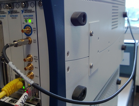

- Important Note! When using a PXI Express chassis use a PXI-6683H as the PXI-6683 will not fit in the chassis. Because it is a hybrid module, it cannot drive the chassis clock directly. So if you check the box to discipline the chassis clock to a time reference you must connect the "CLK OUT" on the front of the PXI-6683H to the "CLK 10 IN" on the back of the PXI Express chassis. A simple SMB to BNC cable works well.
- (Optional) If desire more precision than your Time-Based Syncrhonization module offers, you can add a System Timing Module (i.e.PXI-6653 or PXIe-6674T) to improve precision
Known Issues
- NI VeriStand will shut down a few minutes after deployment due to a watchdog error if you deploy a system definition that specifies the Chassis TimeSync custom device use an external time reference and that time reference was significantly different than the current system time. To work around this issue, either redeploy after the shut down (time has been corrected at that point), or configure the time reference for your Time-Based Synchronization module in MAX and then wait a few minutes before deployment.
- NI VeriStand 2011 does not honor the setting of a Timing and Sync device being the chassis master device. (CAR 351622) Therefore you cannot use this device to generate a sample clock for your signal based single point devices (DAQ, FPGA).
- R Series FPGA devices do not synchronize (PLL) to the PXI chassis clock by default. This must be enabled by going to RIO Device Setup in your start menu. Without this enabled, you could have time drift issues with buffered data coming from R series FPGA devices.
- This custom device does not work on Windows or VxWorks
- When using a larger PXI chassis (like 18 slots) with multiple trigger bus segments, this device does not automatically configure the routing accross the multiple trigger bus segments. This can cause a deployment timeout. Workaround: Find the target in MAX, select the chassis, and manually route away from the segment containing the PXI 6682/6683 on PXI_Trig0. Detailed instructions here.
Version History
1.1.0
- Added support for the PXI-6683 and the PXI-6683H
- Added new "Free Running (internal)" option for a time reference
- Removed the pop up dialog warning that the time reference selection was adjusted when selecting the checkbox to discipline the chassis clock to the time reference and the time reference was "PXI Chassis Clock"
- If the reference selection is adjusted from "PXI Chassis Clock" after the checkbox to discipline the chassis is checked, it is no longer adjusted to 1588. It is now adjusted to "Free Running (internal)". You can always select 1588 yourself is desired.
1.0.0
- Released
Support and Contact
This add-on is provided as open-source software. If it does not meet your exact specification, you are encouraged to modify the source code to meet your needs. It is not officially supported by National Instruments.
If you encounter a problem with this add-on, or if you have suggestions for a future revision, please post to the forum for this add-on Chassis TimeSync Custom Device Feedback. You must use this feedback forum for support. Do not call National Instruments for support for this add-on.
National Instruments does not support this code or guarantee its quality in any way. THIS EXAMPLE PROGRAM IS PROVIDED "AS IS" WITHOUT WARRANTY OF ANY KIND AND SUBJECT TO CERTAIN RESTRICTIONS AS MORE SPECIFICALLY SET FORTH IN NI.COM'S TERMS OF USE (http://ni.com/legal/termsofuse/unitedstates/us/).
- Mark as Read
- Mark as New
- Bookmark
- Permalink
- Report to a Moderator
Stephen,
I followed the steps listed and tried to deploy but I get an error message saying the VI is not executable. Could you please contact me and I can go over this? As soon as I remove the Chassis TimeSync under timing and Sync, I could deploy the sys def.
Thank you
- Mark as Read
- Mark as New
- Bookmark
- Permalink
- Report to a Moderator
Hi Usman,
Sorry to hear that. I will reply in the forum thread linked above in the "support" section with some advice.
- Mark as Read
- Mark as New
- Bookmark
- Permalink
- Report to a Moderator
Where can i find Veristand 2020 Chassis TimeSync?
