- Document History
- Subscribe to RSS Feed
- Mark as New
- Mark as Read
- Bookmark
- Subscribe
- Printer Friendly Page
- Report to a Moderator
- Subscribe to RSS Feed
- Mark as New
- Mark as Read
- Bookmark
- Subscribe
- Printer Friendly Page
- Report to a Moderator
LIFA Quadrature Encoder
Here is a custom version of LIFA to implement quadrature encoders using an Arduino encoder library (v1.1). I've included a diff file named LabVIEWInterface.ino.diff in unified diff format which shows the parts that have been changed.
How to Use
If you are not currently using a custom firmware, you simply need to upload this custom firmware instead.
Arduino Uno:
- Can only implement a single quadrature encoder on pins 2 and 3. Hook up the A and B channels to these pins.
Arduino Mega 2560:
- Two encoders implemented by default. Encoder 0 is on pins 2 and 3 and encoder 1 is on pins 18 and 19.
- A third encoder may be enabled by uncommenting "// #define ENCODER_OVERRIDE_TWI" (removing the //) and then re-uploading. If enabled, the two wire interface (TWI) cannot be used. This includes the I2C protocol. The third encoder is encoder 2 on pins 20 and 21.
I've tested encoders 2 and 3 an the Arduino Mega 2560 successfully. Encoder 0 did not seem to work on my Mega for some reason but I have used it in the past successfully on this same Mega. I do not currently have an Arduino Uno to test. A US Digital S4-360-250-N-S-B was used.
Please let me know your results and any feedback is appreciated. Thanks.
(Based on LIFA 2.2.0.79)
- Mark as Read
- Mark as New
- Bookmark
- Permalink
- Report to a Moderator
Just find this, great news thanks for sharing.
(not tried yet, but that really was a missing feature in LIFA palet, thanks to fill the hole 🙂
Antoine
- Mark as Read
- Mark as New
- Bookmark
- Permalink
- Report to a Moderator
Hi,
I'm using LIFA Quadrature Encoder. It work verry well
Thanks Nathan_B for giving the best thing to me.
LIFA Quadrature Encoder TEST: http://www.youtube.com/watch?v=XhkvSJKDBbo&feature=youtu.be
This is my project: http://www.mediafire.com/view/ada99s28c31fdso/20131010_192800.jpg
- Mark as Read
- Mark as New
- Bookmark
- Permalink
- Report to a Moderator
Hi,thank you very much for sharing!
Using the Arduino Mega 2560, I was able to get Encoder 1 and 2 to work successfully, but not Encoder 0 (on pins 2 and 3).
Have you tested your Encoder 0 lately? I would like to implement all three encoder inputs on my Arduino Mega if possible.
Thanks for your help!
- Mark as Read
- Mark as New
- Bookmark
- Permalink
- Report to a Moderator
I've not tested it since I posted it but I did test all three successfully back in July when I posted this document. Are you getting errors or any random data?
- Mark as Read
- Mark as New
- Bookmark
- Permalink
- Report to a Moderator
The 'encoder count' value goes from 0 to 1 when I turn on the motor, and then it stops counting. I haven't gotten any errors, and again encoder 1 and 2 work great.
Also, how would you recommend incorporating an index channel into this VI?
Thanks again for your help!
- Mark as Read
- Mark as New
- Bookmark
- Permalink
- Report to a Moderator
I have a robot arm Trainer(type ED-7220). ![e7220c_view[3].jpg](http://forums.ni.com/legacyfs/online/127335_e7220c_view[3].jpg)
It has 6 motors and 6 encoders. I'm trying to control this robot by Arduino Mega 2560.
Does the arduino mega 2560 board implement all six encoder?
Thanks for you help in advance!
- Mark as Read
- Mark as New
- Bookmark
- Permalink
- Report to a Moderator
IIRC, the encoder library says that it can use a single interrupt pin per encoder but will yield less accuracy. I've never used less than the two pins per encoder so it should theoretically possible to use all 6 encoders on a single Arduino. You'll have to modify the code to do it.
- Mark as Read
- Mark as New
- Bookmark
- Permalink
- Report to a Moderator
I'm not really sure what could be wrong with the encoder. Have you ruled out the physical encoder? I.e. try both of the other encoders on pins 2 & 3. Other than that, I can't think of anything at the moment. Have you made any other modifications with the firmware or the LabVIEW subVIs?
- Mark as Read
- Mark as New
- Bookmark
- Permalink
- Report to a Moderator
The physical encoder is in great shape - it works on pins 18 & 19, and 20 & 21. At first I made a few modifications to one of the LabView subVIs, but pins 18 & 19, and 20 & 21 still worked. However pins 2 & 3 have never worked for me.
I just recently re-downloaded your original files and tested again on the same encoder. Again pins 2 & 3 don't work, but the other pins work great.
I then tried testing pins 2 & 3 using the original Arudino code, and I was able to read the pulses from the serial monitor.
Maybe something is wrong with one of the LabView subVIs? I know you mentioned that you weren't able to get your encoder 0 to work either.
- Mark as Read
- Mark as New
- Bookmark
- Permalink
- Report to a Moderator
I forgot about it not working on pins 2 & 3. The last time that I know they worked (because I used them on a project that required them to be on pins 2 & 3) was pre-Arduino 1.0 (with LIFA version 1.3.0.29).
- Mark as Read
- Mark as New
- Bookmark
- Permalink
- Report to a Moderator
Is there anyway to change the code and/or firmware to have the encoder work on pins 2 & 3?
Or would you recommend downgrading to LIFA version 1.3.0.29?
Thanks
- Mark as Read
- Mark as New
- Bookmark
- Permalink
- Report to a Moderator
All three encoders are coded in the same manner and some of the code is actually shared. Everything on the LabVIEW side is literally the same code (the same exact nodes on the block diagram).
Feel free to look at the firmware if you notice anything different. My only suggestion would be to extract the code for encoder zero from the firmware and test it without LIFA.
- Mark as Read
- Mark as New
- Bookmark
- Permalink
- Report to a Moderator
Dear Nathan,
How I can read the encoder 0 on Arduino Uno? Is not working on my board, on Mega 2560 neither.
Regards.
- Mark as Read
- Mark as New
- Bookmark
- Permalink
- Report to a Moderator
Unfortunately, I've been unable to figure out why encoder zero is not working.
- Mark as Read
- Mark as New
- Bookmark
- Permalink
- Report to a Moderator
Yea, I can't figure out why encoer 0 isn't working on my Mega 2560 either. It works great running the code from Arduino, but I can't get it to work in LIFA. If anyone figures this out, please let everyone know!
Thanks
- Mark as Read
- Mark as New
- Bookmark
- Permalink
- Report to a Moderator
I have a decidion for Arduino Uno with connection to pins 2 and 3!
In file LabVIEWInterface.h:
#if defined(__AVR_ATmega1280__) || defined(__AVR_ATmega2560__)
#define DEFAULTBAUDRATE 9600 // Defines The Default Serial Baud Rate (This must match the baud rate specifid in LabVIEW)
#else
#define DEFAULTBAUDRATE 115200
#endif
so, I tried to set bauld rate 115200 in VI and and everything became good 
- Mark as Read
- Mark as New
- Bookmark
- Permalink
- Report to a Moderator
So did you get pins 2 and 3 to work on the Mega 2560 too?
- Mark as Read
- Mark as New
- Bookmark
- Permalink
- Report to a Moderator
No, I don't have Mega to try. You can try to set different baudrates or edit LabVIEWInterface.h to set baudrate without "if". But after reading the code I don't know why mega works only on 18 and 19 pins
- Mark as Read
- Mark as New
- Bookmark
- Permalink
- Report to a Moderator
Yea chanigng the baud rates didn't fix anything for me using an ATmega board. I looked at the code and I couldn't find anything wrong either. It's weird why encoder 0 (pins 2 & 3) works fine running the encoder library from arduino with the ATmega but won't work in LIFA.
Does anyone else have any other suggestions?
Thanks
- Mark as Read
- Mark as New
- Bookmark
- Permalink
- Report to a Moderator
I played around with the firmware a bit, and added my encoders to interrput and non-interrupt pins. Then using 115200 baud, I was still able to read all of the encoder pulses. So problem solved!
Does anyone know how to calculate an accurate speed using this VI? It would be a fairly slow speed of ~10 RPM, and I assume it involves using the "micros()" command in Arduino. Or is there a bette way to implement this in LabView?
Any help, would be much appreiated. Thanks
- Mark as Read
- Mark as New
- Bookmark
- Permalink
- Report to a Moderator
What problem did you solve? Are you saying you got encoder 0 to work (pins 2 & 3)? If yes, what was the solution?
Regarding speed, it would be best to implement that on Arduino because of the unpredictable time required to transmit all of the data being sent to and from the Arduino over serial.
- Mark as Read
- Mark as New
- Bookmark
- Permalink
- Report to a Moderator
No, I didn't get encoder 0 to work on pins 2 & 3, but I got encoder 0 to work on pin 18 (interrupt pin) and pin 22 (non-interrupt pin). I just added some code to the firmware, and I was able to read all of the encoder counts with 115200 baud. So now I'm able to use all 3 of my encoders. I'm still confused as to why pins 2 & 3 won't work on the Mega. I spent a long time going throguh the firmware and couldn't find an answer to this.
For speed, I'm going to try working in the control design module and add a derivative function to the enocder input signal. I think this should work. Have you used LIFA in the control design module before?
- Mark as Read
- Mark as New
- Bookmark
- Permalink
- Report to a Moderator
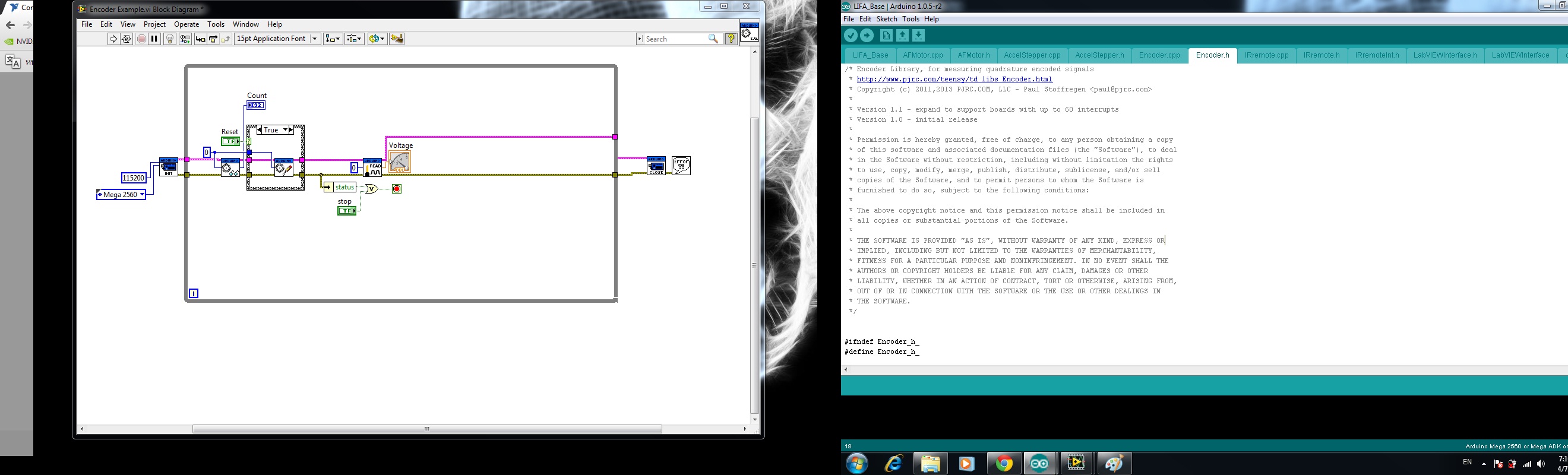
I can't seem to compile the lifa base you have. I get this error...
Encoder\Encoder.cpp.o:(.bss._ZN7Encoder13interruptArgsE+0x0): multiple definition of `Encoder::interruptArgs'
Encoder.cpp.o:(.bss._ZN7Encoder13interruptArgsE+0x0): first defined here
any idea what I am doing wrong???
Thanks!
- Mark as Read
- Mark as New
- Bookmark
- Permalink
- Report to a Moderator
Multiple definitions will probably occur when you have the encoder library installed the "traditional" way. So, you will need to uninstall the encoder library. The LIFA_Base that I have given in the document contains it already (a custom version, IIRC).
- Mark as Read
- Mark as New
- Bookmark
- Permalink
- Report to a Moderator
Hi Nathan:
I deleted the encoder library from the library file (not sure if that is the "traditional" thing to do ...being a C++ noob and all. I'm good on the LabVIEW side of things though! )
and I have your LIFA_Base code in the Sketchbook folder. I navigated to LIFA_Base.ino via windows explorer and clicked on it which opened it in Arduino 1.0.5 I then tried to compile it and got a different error this time...
LIFA_Base.cpp.o: In function `loop':
F:\Arduino Libraries and Such\Arduino-1.0.5/LIFA_Base.ino:59: undefined reference to `checkForCommand()'
F:\Arduino Libraries and Such\Arduino-1.0.5/LIFA_Base.ino:65: undefined reference to `sampleContinously()'
LIFA_Base.cpp.o: In function `setup':
F:\Arduino Libraries and Such\Arduino-1.0.5/LIFA_Base.ino:39: undefined reference to `syncLV()'
I'm not sure what to do now. Should I move a portion of your code to the library???
I appreciate your help and thanks for that speedy reply yesterday,
Dave
- Mark as Read
- Mark as New
- Bookmark
- Permalink
- Report to a Moderator
You shouldn't need to move any of my code (in fact, if you do, it won't work). The errors that you are seeing now usually happen when the Arduino IDE does not open all the required files for the sketch. The best way to open Arduino files is to first just open the Arduino IDE. Then, Choose "Open Sketch" or "Open" from the file menu and browse to the LIFA_Base.ino. This should then open all the files in the Arduino IDE and allow you to compile.
- Mark as Read
- Mark as New
- Bookmark
- Permalink
- Report to a Moderator
hi every body, i just add :
// Place your custom setup code here
pinMode(2,INPUT);
digitalWrite(2,HIGH);
pinMode(3,INPUT);
digitalWrite(3,HIGH);
in LIFA_Base.ino file and get Encoder0 works in 2 & 3 pins. hope this can helps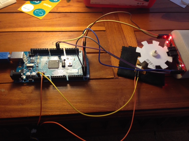 you.
you.
- Mark as Read
- Mark as New
- Bookmark
- Permalink
- Report to a Moderator
Hi Nathan and Y203901:
Thanks for your suggestions. I deleted everything and then reinstalled your LIFA_Base and recompiled and opened it as you suggested Nathan. It compiled!
I then opened LabVIEW and ran the example program but couldn't get it to read until I inserted the code that Y203901 put in his comment and now it runs perfectly!
Thanks to both of you!
Dave
- Mark as Read
- Mark as New
- Bookmark
- Permalink
- Report to a Moderator
Just as an FYI to all, setting a digital pin mode to INPUT and then writing a HIGH value to it enables the internal pullup resistor. I recommend that this be done in LabVIEW instead so that if not using one of the encoders, those particular pins will not be affected.
I will have to test this to verify and I might add it into the library if it is deemed a requirement for all encoders.
- Mark as Read
- Mark as New
- Bookmark
- Permalink
- Report to a Moderator
Now it works with UNO too
- Mark as Read
- Mark as New
- Bookmark
- Permalink
- Report to a Moderator
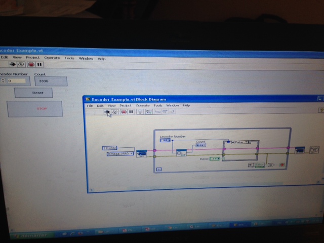
hello mr nathan
i really need ur help
i need to interface my arduino with labview. when i am doing it i am having error like ''java'' and it is not compiling
sir i have another diff issue. sir u know am trying to program an encoder dc geared motor, i did the coding, the circuit, i am getting the reading also
here is it
now how to proceed to do specific positioning because the encoder reading is very fast
help me please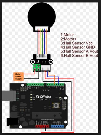
- Mark as Read
- Mark as New
- Bookmark
- Permalink
- Report to a Moderator
hello
I'm trying to modify the file LIFA encoder , according to the encoder speed to provide a EMG30 engine can send the speed to labview, or assign a PIN PWM value according to that speed.
Someone could help me?
thanks
- Mark as Read
- Mark as New
- Bookmark
- Permalink
- Report to a Moderator
hello i am noob in LIFA i need to add code from
where to add this code
pinMode(2,INPUT);
digitalWrite(2,HIGH);
pinMode(3,INPUT);
digitalWrite(3,HIGH);
i can work only pin1 (18,19) but i need to work on two encoder
and i can't work pin2 (20,21)
Thanks
- Mark as Read
- Mark as New
- Bookmark
- Permalink
- Report to a Moderator
You can enable pull-up resistors via LIFA (which is what I recommend) i.e. you don't need to change the firmware to do this part.
In the image you posted, there is only one encoder. To use encoder 2 (pins 20 and 21) you have to enable it (which disables I2C) by modifying the firmware that i have provided as stated in the document above.
- Mark as Read
- Mark as New
- Bookmark
- Permalink
- Report to a Moderator
Hi Nathan_B
Sorry i don't understand about pull-up resistors and I2C
i am noob all C++ and Labview. now i uncertain that i wire is correct in pic (encoder have 5V GND A B)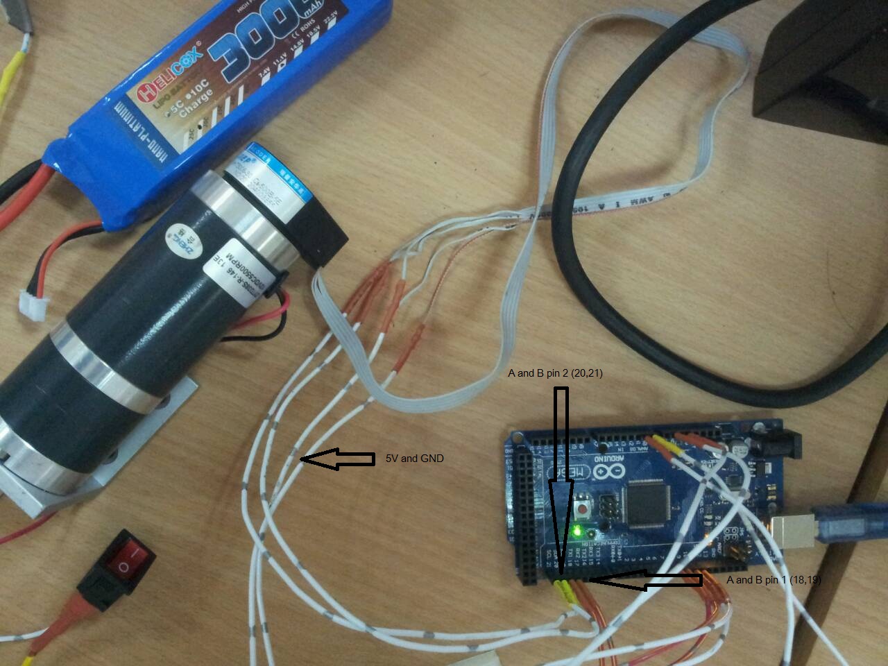
and i can work pin 1 (18,19) but can't work pin2 (20,21)
.jpg)
.jpg) and i try two encoder but i think my code was wrong
and i try two encoder but i think my code was wrong
Thanks for your help
- Mark as Read
- Mark as New
- Bookmark
- Permalink
- Report to a Moderator
To get pins 20 and 21 to work, you have to enable them manually in the firmware that I have uploaded above. Read the section of the document that talks about the Arduino Mega 2560, it explains what you need to do to enable these pins to work as an encoder. Did you do that part?
The Arduino code that you posted on April 7 is used to enable pull-up resistors.
- Mark as Read
- Mark as New
- Bookmark
- Permalink
- Report to a Moderator
Hi Nathan_B
Now i can work with two encoder with pin1(18,19) pin2(20,21) when i read document above clear and uncommenting "// #define ENCODER_OVERRIDE_TWI" (removing the //)
Thanks so much for your help
- Mark as Read
- Mark as New
- Bookmark
- Permalink
- Report to a Moderator
Hi Nathan_B
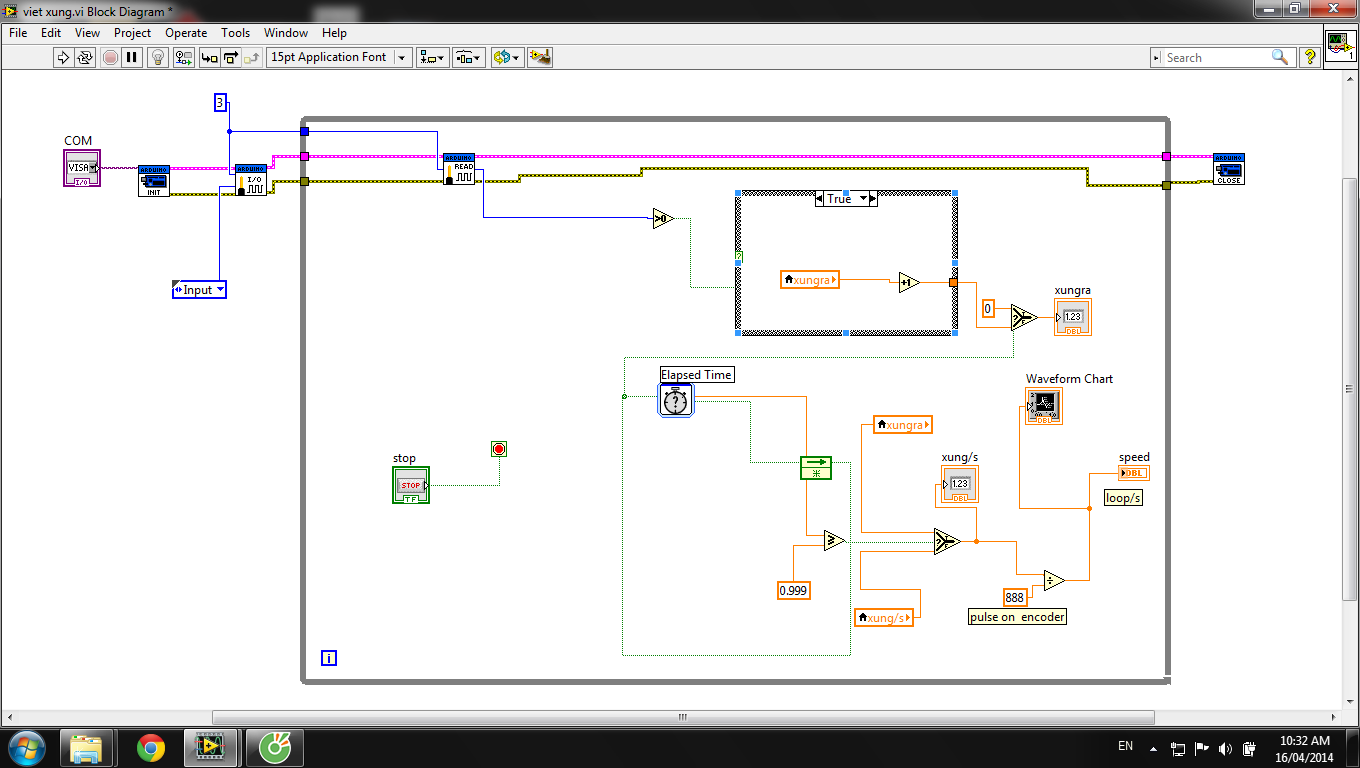
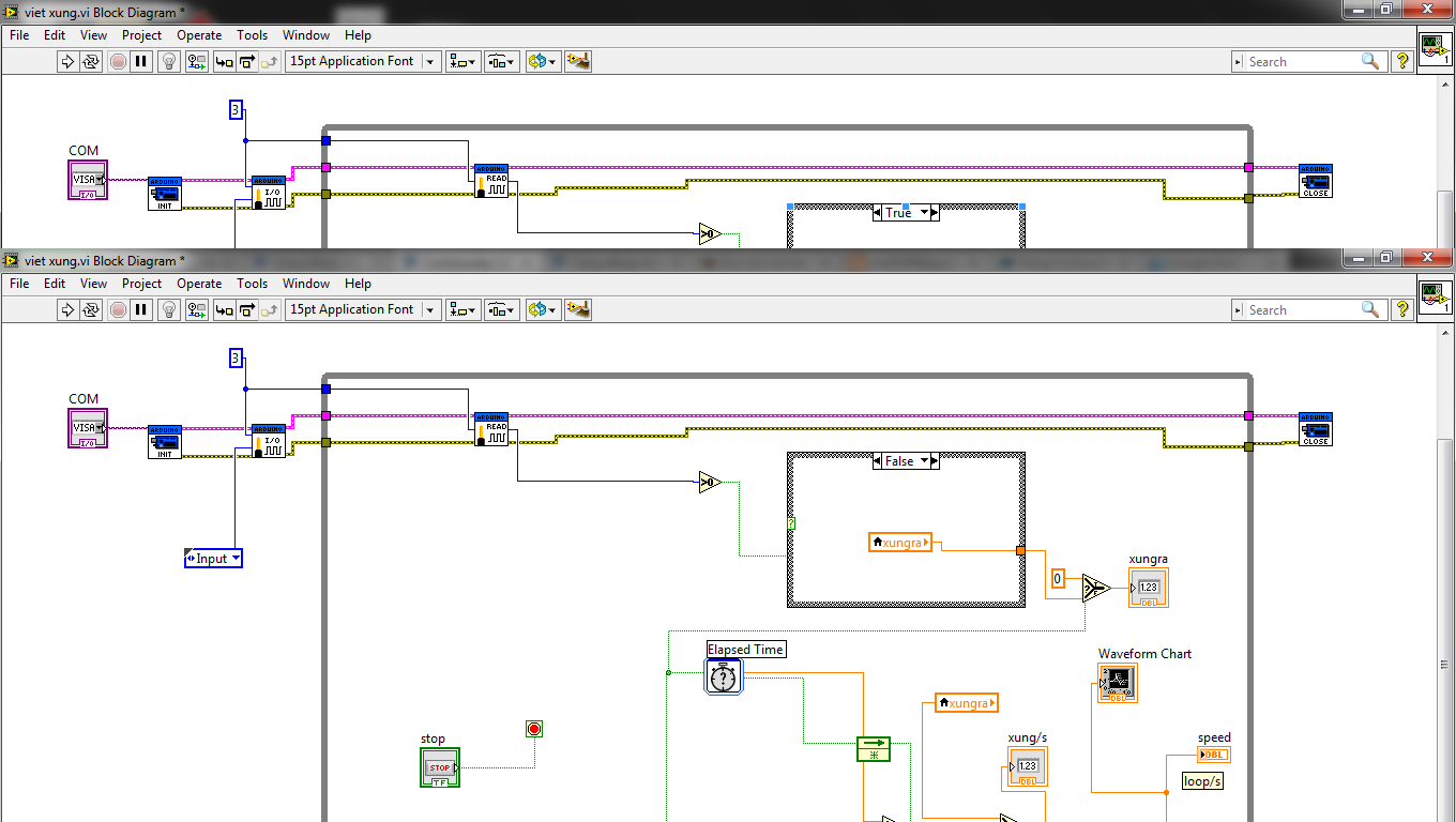
i am doing project :. Controls PID DC (DC 12V with encoder 888 pulses / past) with the Arduino uno and connect to LabVIEW . I use LIFA_Base file but it does not seem correct in my project. In 1 seconds, Pulses displayed in LabVIEW less than real. i don't know why, you can help me.
this is my project :

If you have the Project same same Project of me, could you send to me with the mail: mir.baobao @ gmail.com . thanks you very much.
- Mark as Read
- Mark as New
- Bookmark
- Permalink
- Report to a Moderator
Based on the images of your VI, you are not using the functionality that I have provided in the document. You are simply reading a digital pin. This method will not work reliably as you have just experienced.
The document above is for using quadrature encoders and I have not tested it using a plain incremental encoder. I recommend trying the encoder VIs that I have provided above to see if that works.
- Mark as Read
- Mark as New
- Bookmark
- Permalink
- Report to a Moderator
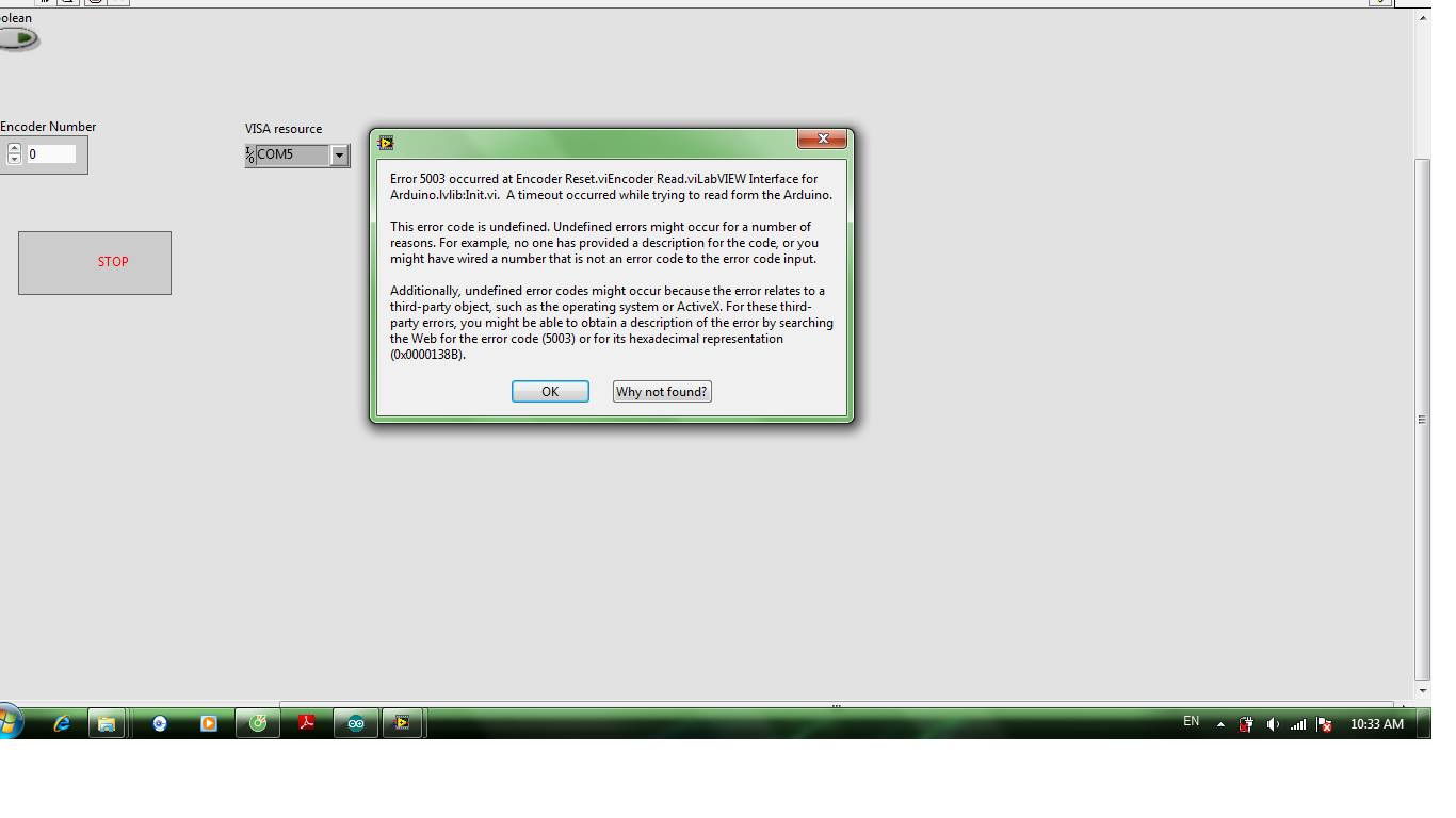
I have tried to 12V DC 888 pulses, pulse out and it does not give error 5003, asked him to help me!
- Mark as Read
- Mark as New
- Bookmark
- Permalink
- Report to a Moderator
I don't understand your statement.
- Mark as Read
- Mark as New
- Bookmark
- Permalink
- Report to a Moderator
I have DC 12V with Motor parameters:
- 3V 60mA 70rpm
- 6V 70mA 140rpm
- 12V 80mA 280rpm
and encoder 888 P/R
http://banlinhkien.vn/goods-2443-dong-co-encoder-888-xung.html#.U1CjNCEuCQw
In 3,3V: it work , pulses show in ladview is 62000 pulses
In 5V to 12V: it don't work. In labview show error 5003
do you know why? in my opinion, In 5V to 12V, too pulses, so labview can not count.
please help me, thanks you very much
- Mark as Read
- Mark as New
- Bookmark
- Permalink
- Report to a Moderator
Hi Nathan:
By the way, thanks for all the support you have given with respect to the LIFA Encoder. Recently, I have combined an encoder (on interrupt pins 2 and 3) with a limit on pin 4 and a stepper motor output pulse on pin 10.
Using your encoder VI's and the LabVIEW digital write/read vi's. I attempted to write a train of digital pulses to the stepper motor in an effort to create an encoder feedback on the position and a limit for determining the home position. In creating the pulses I write a 1 wait then write a 0 and wait then I check the limit and encoder position. This keeps looping depending on how close the encoder postion is to the desired position or if a limit has been reached. However, I noticed that as soon as I send pulses to pin 10, the encoder reading is all over the place and even my digital limit value ranges between zero and 255 (which is really strange since I would expect the output to be either 0 or 1!)
We isolated many parts of the circuit in order to rule out cross-talk between pin10 (the pulsed output) and pins 2,3,4 (digital inputs). We also checked pins 2, 3 and 4 with a scope while sending a pulse out on pin10 and they were exactly as they should be. The readings in LabVIEW however were all over the place.
The only conclusion that we could come to is that there is something in the uC code that is causing the problem. Possibly some incompatibility with your extended encoder function? It doesn't appear to be your code though, that I can tell. If I disconnect the motor so that the encoder isn't setting off interrupts to the uC, the values are still all over the place in LabVIEW when I send pulses out on pin 10. I'm thinking values are getting written to a global variable or something except that the values go from say 65 to 80493 for example. Maybe more likely is that there is some communication problem which is sending spurious values to LabVIEW. Have you seen this before?
Anyhow, I was hoping to see if you had any insight into this dilemma.
Thanks very much,
Dave
- Mark as Read
- Mark as New
- Bookmark
- Permalink
- Report to a Moderator
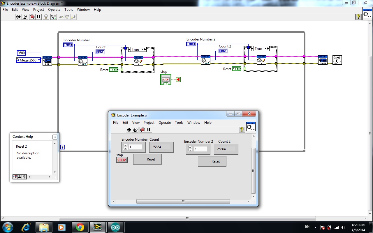
Hi Nathan_B
With this custom LIFA quadrature encoder, labview is the reading value of encoder connected to my arduino 2560 on pin 18 & pin 19. since the motor is runing continuously , the counter is continuously getting incrementated. I just want to know that which encoding technique(x1, x2. & x4) of quadrature optical enoder is used by Labview when it uses the encoder 2 of aurdino mega 2560 ??
Thanks in advance
- Mark as Read
- Mark as New
- Bookmark
- Permalink
- Report to a Moderator
It's using either two or four. Whatever the default is for the encoder
library in the firmware that is attached.
- Mark as Read
- Mark as New
- Bookmark
- Permalink
- Report to a Moderator
still confused 
how can i get access to the library ?. I have just download LIFA quadrature and it is working very well . what is happening at the back end i have no idea. My final job is calculate the velocity of motor for that I have to use the farmula which depends upon the encoding technique used by arduion to read the encoder .. please help me out here.
- Mark as Read
- Mark as New
- Bookmark
- Permalink
- Report to a Moderator
Simply get the change in value of the encoder counts from the VI when you
rotate the encoder 1 revolution experimentally. This gives you the
conversion factor you need, counts per revolution.
- Mark as Read
- Mark as New
- Bookmark
- Permalink
- Report to a Moderator
ahaaan.. thanks , its really a good idea. I would use it but after your first comment I searched the library <encoder.h > and got to know that the it is using x4 technique . and with the farmula
from the site "http://www.ni.com/white-paper/7109/en/" I can calculate the current position of my encoder. x= the coding technique . N= counts per revolution . Now my task is to calculate the velocity RPM . how can I do it ?
The immediate idea which is comming in my head is to keep track of the time for my motor is runing and then divide the current position(read by encoder) with time.. is there any better way to get this done .?
Thanks
- Mark as Read
- Mark as New
- Bookmark
- Permalink
- Report to a Moderator
Simply use the definition of velocity: change in position divided by change in time. If you are not familiar with this concept, take a look at any basic Physics textbook or search online. In your case, it will be rotational velocity.
- Mark as Read
- Mark as New
- Bookmark
- Permalink
- Report to a Moderator
Hi Nathan
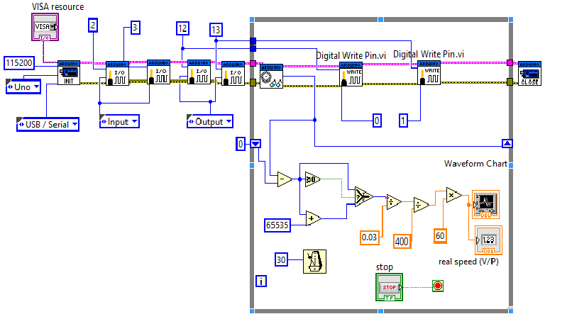
I am doing projet: measure the speed of DC motor. I am using the functionality that you have provided in the document. but I have a problem, the speed is not stabilty, it fluctuates around a value. I use Arduino Uno and encoder 100 pulses. Can you help me, please
Thanks
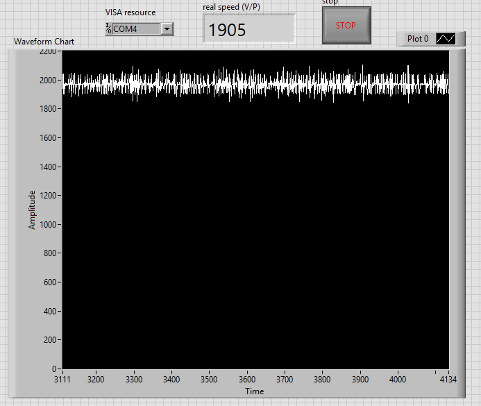
this is my block diagram