How to Combat Channel Switching caused by FPGA FIFO Overflow
- Subscribe to RSS Feed
- Mark as New
- Mark as Read
- Bookmark
- Subscribe
- Printer Friendly Page
- Report to a Moderator
Code and Documents
Attachment
Overview
This example shows how to combat channel switching caused by FPGA FIFO overflow.
Description
When sending multiple channels of data over an FPGA FIFO it is common to interleave the data. Unfortunately, if an overflow occurs, channel switching can also occur, as the interleaved data is decimated in the wrong order. To combat this the data from multiple channels can be combined together into one larger element. Whilst this method does not prevent data loss (see articles on increasing FIFO size and depth for help with this matter) it does mean that if overflow occurs, channel switching is prevented as all data points will be removed.
Requirements
- LabVIEW 2012 (or compatible)
Steps to Implement or Execute Code
- Add Real-Time device and FPGA target to the project (If the device is not available, a simulated one would also work).
- Run the VI. (If the simulated device is used, then the VI needs to be dragged from the Real-time target to "My Computer" in LabVIEW Project Explorer.)
Additional Information or References
VI Block Diagram


**This document has been updated to meet the current required format for the NI Code Exchange.**
Example code from the Example Code Exchange in the NI Community is licensed with the MIT license.
- Mark as Read
- Mark as New
- Bookmark
- Permalink
- Report to a Moderator
This works if you have 4 channels. If you want to use N channels: On the FPGA, first check the available FIFO space before adding elements. If space is available, then add your array of channels.
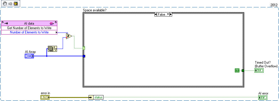
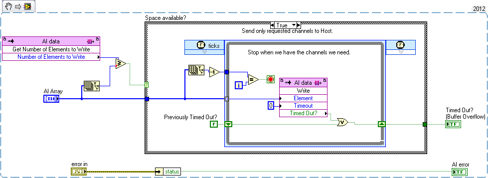
On the host side, you do things as usual : grab a number of samples that is a multiple of the number of channels.
