Overview
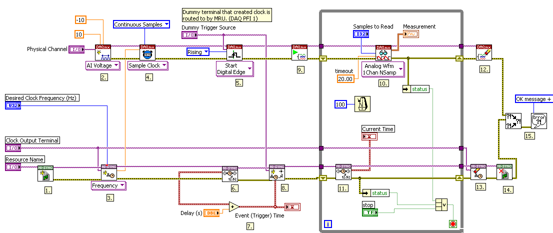
This example demonstrates how to use NI-Sync, along with a Timing & Synchronization board and DAQmx, to create and send a sample clock and a start trigger to a DAQmx device.
Description
This program uses the NI-Sync API to create a clock based on a time reference set in MAX. The user inputs a time delay for when they would like the acquisition to start relative to the time reference. The clock is then routed to the DAQmx sample clock source terminal of the DAQmx Timing VI. When the Event, or trigger time, occurs after the defined delay, then a start trigger is sent to the DAQmx device and acquisition begins and data is output to a graph until the user stops the program or an error occurs.
Requirements
Software
- LabVIEW 8.5.1 or compatible
- DAQmx 8.9 or compatible
- NI-Sync 3.0 or compatible
Hardware
- PXI Chassis
- PXI M-Series or E-Series DAQ Board
- PXI-6682 Timing & Sync Board
Steps to Implement or Execute Code
1. Select the Physical Channel of the DAQmx device you are using.
2. Select the Timing & Synchronization board you are using. Make sure that the board is in the timing slot of the PXI chassis (slot 2).
3. Select any PXI_Trig line for clock routing (The MRU will take care of the exact route).
NOTE: The MRU (mx Routing Utility) takes a survey of what resources are being used and selects the best route for signals.
4. Select the Clock Frequency.
5. Select the number of samples to be read.
6. Select the dummy trigger source terminal, this can be any PFI line. (once again, the MRU takes care of the exact routing).
7. Select the delay from the time reference in seconds.
Additional Information or References
Export Sample Clock_Trigger_FTE with GPS status_LV86.vi - Adds some GPS status indicators on the front panel
**This document has been updated to meet the current required format for the NI Code Exchange.**
