- Document History
- Subscribe to RSS Feed
- Mark as New
- Mark as Read
- Bookmark
- Subscribe
- Printer Friendly Page
- Report to a Moderator
- Subscribe to RSS Feed
- Mark as New
- Mark as Read
- Bookmark
- Subscribe
- Printer Friendly Page
- Report to a Moderator
Controlling a USB LiDAR using myRIO and the 'Classy' State Machine
What's contained in this example?
Last time, I showed you how the URG-04LX could be controlled from a PC running LabVIEW. This time, let's make this application portable by controlling it from a myRIO instead!
In this example, we show how the myRIO can be used to control a connected USB device via the onboard USB Host port, and get it to return data over a network back to our development machine. We also introduce a novel design pattern called the Classy State Machine, which allows us to define an extendable architecture for implementing flexible programmatic control of the operation of a remote target such as the myRIO within LabVIEW.
What hardware and software will I need?
You will need access to a myRIO and a powered Hokuyo URG-04LX or URG-04LX-UG01 LiDAR. The LiDAR must be connected to the myRIO via the USB Host Port (The Connector Type A at the top of the myRIO). This project was written in LabVIEW 2013, so you'll need this version or higher.
What will I learn?
This one isn't for the feint of heart! This example deals with quite a few advanced LabVIEW features such as LabVIEW Object Oriented Programming (LVOOP), the NI-VISA USB RAW APIs, Network Streams, Event Structures, and also needs you to be familiar with remote device configuration schemes such as SSH.
How do I get started?
- Download the attached file myRIO URG_04LX.zip containing all project documents.
- Connect to your myRIO via a network connection or directly via USB link so that it becomes visible in MAX. Need help getting the device visible?
- SSH into the device, and enter your adminstrator credentials.
- Execute the command rmmod cdc-acm from the command line (Video). Huh?
- Unzip the attached file and open up the contained LabVIEW project myRIO URG_04LX.lvproj.
- Specify the IP Address of your myRIO within the Project Explorer. Remote Devices » myRIO » Properties » Network Address
- Execute RT Main.vi.
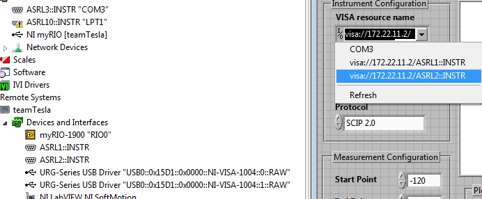
- Open Host Main.vi and specify the IP Address of your myRIO (Figure 1.0).
- Finally, execute Host Main.vi. You should now be able to make height measurements from the LiDAR using the myRIO, and transmit these measurements over your network connection for analysis in LabVIEW! Try adjusting the parameters of LiDAR Configuration to see how we can interact and change the format of the acquisition at run time.
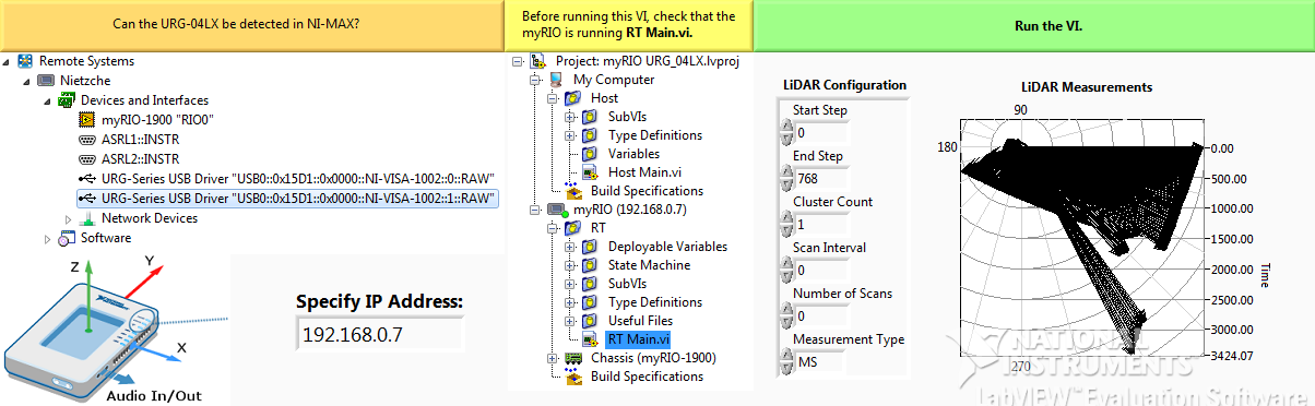
Figure 1.0 : Front Panel
So, how does it work?
There's quite a few things going on in this example that won't be immediately apparent. Here you'll find a brief description, however for a full understanding you must try working through the LabVIEW project to see the guts of how this has been implemented. If you have any questions, please feel free to leave a comment!
This example relies on the following requirements; the myRIO must be able to acquire height measurements from the URG-04LX range finder and simply transmit these measurements back to our host application running on a PC. However, where things get interesting is that we'd like to be able to control the state of the myRIO from our PC so that we can customise the format of the acquisition. There are existing examples of how this can be achieved using Shared Variables; but in this example, we aim to use a different scheme called the Classy State Machine (CSM) (Figure 1.1). The CSM is an implementation of the common State Machine design pattern, but instead of relying on an enumerated constant to represent the state, we use LabVIEW classes.
The purpose of the CSM is as follows:
- Provide external asynchronous control of a remote target. (Change what a remote target is doing at our whim.)
- Allow us to buffer a set of states we'd like our remote target to work through procedurally. (Make sure we can make our remote target work through a bunch of states in order.)
- Ensure that each state is initialized with every data dependency before it is executed. (Promise that whenever a state is executed, it has all of the things it needs.)
- Implement a very tight relationship between the function of a state and the data it is dependent on. (Make it clear to the programmer what data a state needs, and make sure no other states need it unless it's vital!)
- Allow us great flexibility in implementing additional behaviour to our target, without significant reprogramming of the governing architecture. (If we want to add a new state, we just need to create a new state class, not program the new state directly into our target.)
The CSM works by using a Network Stream to buffer different kind of LabVIEW objects (Runtime instances of a class) which all inherit from a class called Generic State. Generic State contains all of the data common to all states, accessors to this data, and two dynamic dispatch methods 'Execute State' and 'Process State Environment.vi'. Fundamentally, all the CSM does is iterate through all types of Generic State objects that have been transmitted across the Network Stream and call the Execute State method for each state in order. That state is then thrown away. The flexibility in this pattern comes from the fact that we can make a huge array of classes that extend Generic State, so that their implementation of Execute State can do all kinds of interesting things; literally whatever we want! This means that our target device, in this case the myRIO, only needs to run a single CSM, and yet perform an astonishing variety of behaviour! All we need to do is create a different LabVIEW classes that extend Generic State, defining their own arbitrary functionality within Execute State!
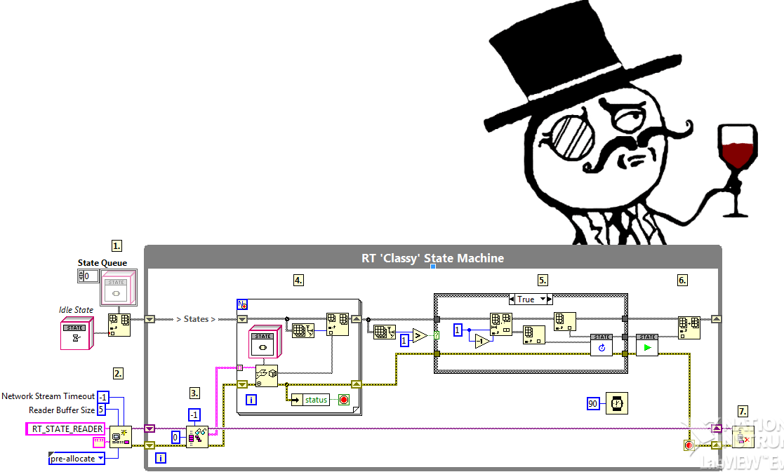
Figure 1.1 : The Classy State Machine Design Pattern (Real Time)
How do we configure the LiDAR?
Additionally, this example shows how we can use the VISA USB RAW APIs to configure a connected USB device (Figure 1.2). Specifically, we discuss the critical operations that need to be executed when initializing control of a USB device which inherits from the Communication Device Class (CDC). The specified parameters used to configure the URG-04LX are not available online, and for this task the use of a USB Packet Sniffer was needed in order to asses which flags needed to be set in order to construct a viable connection.
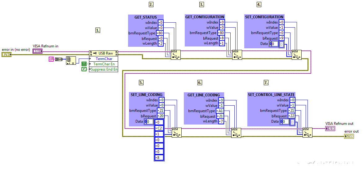
Figure 1.2: VISA USB RAW Configuration of the Hokuyo URG-04LX
- Mark as Read
- Mark as New
- Bookmark
- Permalink
- Report to a Moderator
Hi Alex,
Thanks a bunch for this tutorial. I am working with the myRio and the URG-04LX for localization of an autonomous robot within a room.
I am having a bit of trouble getting the URG-04LX to connect to the myRio, specifically I am unable to see it in NI MAX. Are you using a powered USB hub or have you connected directly to the myRio? Are there any other drivers you need to install?
I have done your previous tutorial for connecting the URG-04LX directy to the computer and it worked like a charm. Hopefully you are able to help me here.
Thanks again,
Brook Dyer
- Mark as Read
- Mark as New
- Bookmark
- Permalink
- Report to a Moderator
Hey Brook,
Sorry for the delay in getting back to you. I used to be reliable. No, really.
It's good to hear that my other example worked... That's something!
The thing that sticks out the most to me in your post is that he LiDAR can't be powered just from the bus; you'll see that the URG-04LX has two ports, the USB port and a serial connection. You'll need to provide a second power input via the serial port in order for the LiDAR to power on properly. This is because it draws a lot of current.
I'd used all of the factory defaults for the myRIO, but upgraded to the latest version of NI-VISA and installed all of the extras that come with it. I hope this helps.
Please make sure that the associated Network Variables have been deployed too. You'll find them in the Project Explorer.
Your application sounds really cool; it'll be nice to see the results!
- Mark as Read
- Mark as New
- Bookmark
- Permalink
- Report to a Moderator
Hi Alex,
Thanks for the reply  I meant to say that I was using the URG-04LX-UG01! Not sure why I left out the UG01, I guess I assumed they were the same thing. This unit is only powered by USB, will it be able to run via USB from the myRio alone?
- Mark as Read
- Mark as New
- Bookmark
- Permalink
- Report to a Moderator
Hi Alex,
I managed to get it to show up Updating VISA and reinstalling the software on the myRio did the trick.
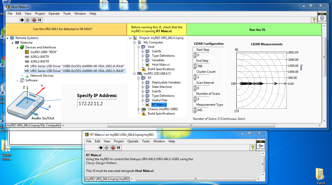
I am able to run the project, although the output of the LiDAR are not what I expected. Does this look right to you? If not do you know how to fix this? The LiDAR is working fine when connected directly to the PC.
Sorry to be a pain!!
Brook
- Mark as Read
- Mark as New
- Bookmark
- Permalink
- Report to a Moderator
Hey Brook,
That's great news. Getting the URG to show up in MAX is the biggest issue, no doubt!
That output doesn't look too right. Do the values vary, at all? Or are they constant?
I've not actually tested this code with the UG01. I know they're quite similar, but one thing I have found is that the UG01 doesn't expect the command phrase "SCIP 2.0\n" when we start communicating with it. How does the LiDAR behave? For example, does the LED come on when the application starts? This shows that the laser has been turned on. That will show that we're at least writing the correct data.
Just a hunch, but have you completely powered down the module, then powered it up and connected it to the myRIO, without connecting it to a PC first?
Hope this helps.
- Mark as Read
- Mark as New
- Bookmark
- Permalink
- Report to a Moderator
 hi Alex
thanks for your previous reply
the lidar is visable to MAX now but still invisablle to VISA, means i can't create a constant like you did in RT MAIN.VI http://forums.ni.com/t5/LabVIEW/myRIO-VISA-Error-1073807192/td-p/2747056
and facing same problem as bdye815's
really appreciate if you could help
- Mark as Read
- Mark as New
- Bookmark
- Permalink
- Report to a Moderator
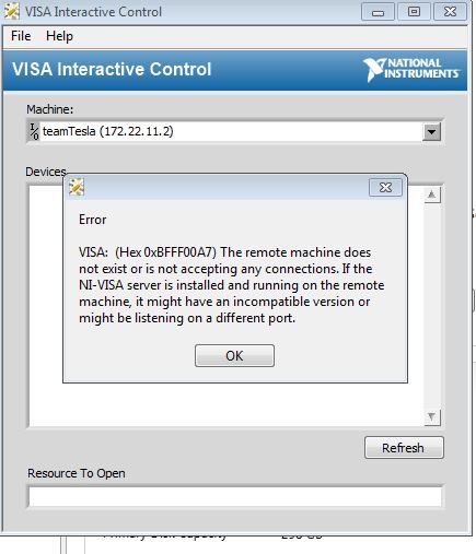
just find a an error when i try to interactive visa, does it a matter?
- Mark as Read
- Mark as New
- Bookmark
- Permalink
- Report to a Moderator
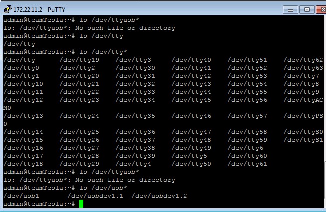
had another look
the result of executing ls /dev/ in putty
is usbdev1.2 or 1.3 but ttyusb+something
so do i have to adjust file S10SetLnUSB accordingly
- Mark as Read
- Mark as New
- Bookmark
- Permalink
- Report to a Moderator
i am experiencing same result as shown in your picture.
the lidar reading likes a black line retracting fore and back, thin and thick.
- Mark as Read
- Mark as New
- Bookmark
- Permalink
- Report to a Moderator
Hi guys, I having some trouble for the myRio to recognise the URG-04LX as a USB device
at the moment i can only commuincation with the lidar with UART using the labview lidar library, but im getting really slow data rate (like 1s delay). I have tried typing in "the command rmmod cdc-acm" but it didnt really help.
So how can I make the lidar to be recognised as a USB device so that i could use this project? Or is there any good way to speed up the data rate with the UART communication??
Any help would be appreciated!! thanks
- Mark as Read
- Mark as New
- Bookmark
- Permalink
- Report to a Moderator
CaVon, welcome!
Can you post the results of the following commands right after (unplugging then) plugging in the lidar?
dmesg | tail -n 20
lsmod
- Mark as Read
- Mark as New
- Bookmark
- Permalink
- Report to a Moderator
Hi BradM, thanks for the reply! here is the results u wanted
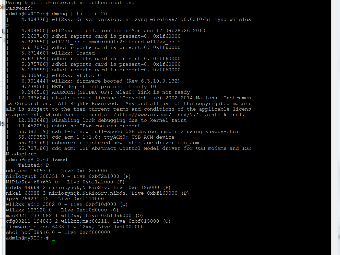
I powered up the lidar without the usb in, then i plugged the usb in and run those commands.
thanks!
- Mark as Read
- Mark as New
- Bookmark
- Permalink
- Report to a Moderator
CaVon,
I would recommend doing the following (from the console):
mv /lib/modules/*/kernel/drivers/usb/class/cdc-acm.ko ~
depmod
This will remove the cdc-acm module from being loaded by the kernel when a CDC-ACM device is plugged in (since VISA code is handling the interaction, the kernel driver actually gets in the way)
- Mark as Read
- Mark as New
- Bookmark
- Permalink
- Report to a Moderator
I did your suggested command:
mv /lib/modules/*/kernel/drivers/usb/class/cdc-acm.ko ~
depmod
and get this this messge from the console after doing dmesg | tail -n 20 and lsmod again.
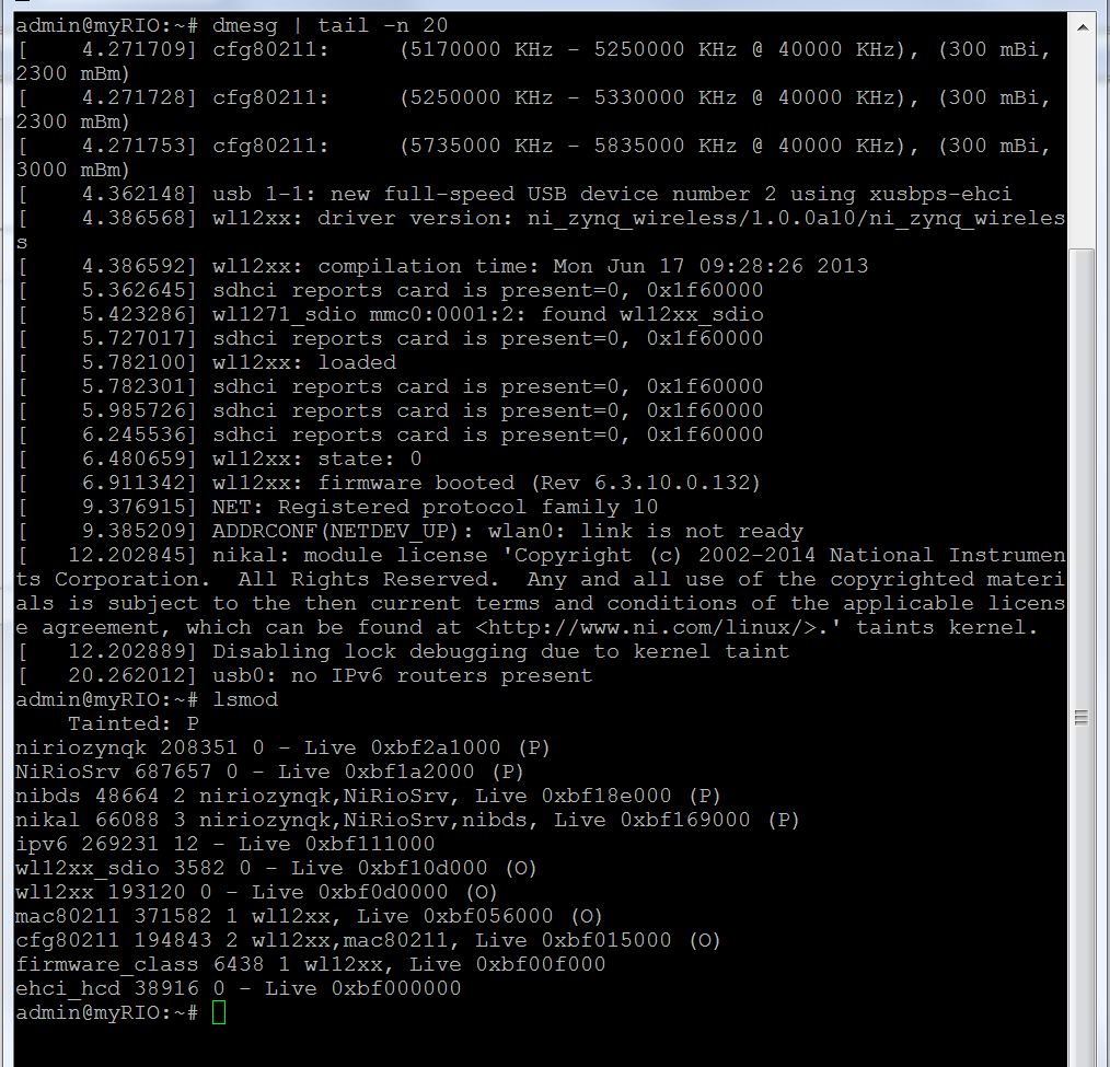
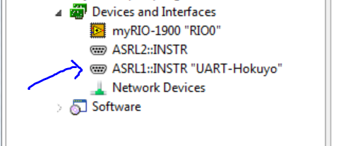
but it still doesnt show up in MAX: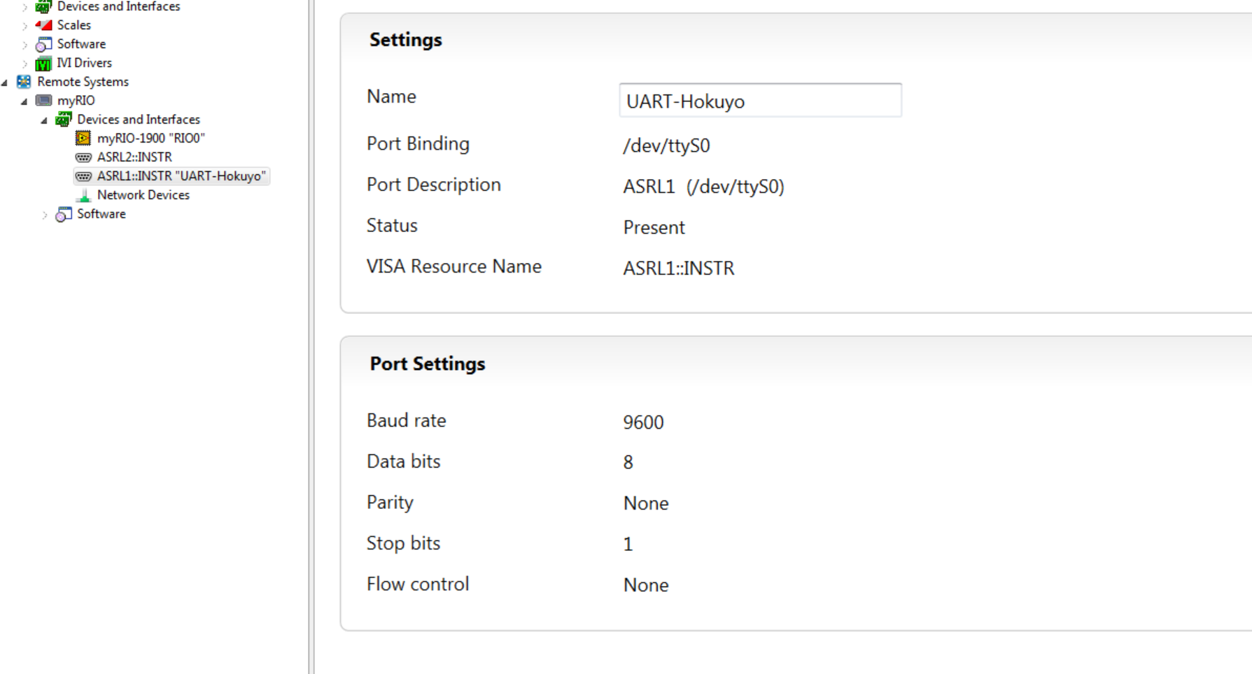
the weird thing is, that UART-Hokuyo is there no matter what (even when I unplug/power down the laser).
then I tried retyping the mv command again and it says no such directory, so the file has definitely been moved.
ArduinoMosfet from this thread:http://forums.ni.com/t5/LabVIEW/myRIO-VISA-Error-1073807192/td-p/2747056 , seems to have the same problem as me and I have basically tried everything he tried.
Anyway thanks for your effort in helping again
- Mark as Read
- Mark as New
- Bookmark
- Permalink
- Report to a Moderator
Hmm, well the driver is indeed no longer loading, but I have to admit that I am not too familiar with VISA's handling of devices. The fact that the device shows up in MAX even with the device not present is probably due to the fact that the UART link at /dev/ttyS0 exists even if the device does not.
- Mark as Read
- Mark as New
- Bookmark
- Permalink
- Report to a Moderator
Yea Im kinda giving up on the USB. Thanks for helping anyway
- Mark as Read
- Mark as New
- Bookmark
- Permalink
- Report to a Moderator
Solution for the device-recognition (USB):
Update VISA, open NIMAX, browse to the myRIO, click on software, click on "add or remove software" (I don't know the exact description in english 😕 ) (the button is locatet at the upper part).
Look for the checkbox named something like USB-drivers and CHECK IT. Click on save and restart the myRIO...
It should work
Aaron
- Mark as Read
- Mark as New
- Bookmark
- Permalink
- Report to a Moderator
Thanks for the update, ArduinoMosfet!
- Mark as Read
- Mark as New
- Bookmark
- Permalink
- Report to a Moderator
Alex,
The results which I am getting is the same as Brook got.. I am getting a constant value of the magnitude which is 19.. I tested PC version: https://forums.ni.com/t5/Example-Code/Using-LabVIEW-and-the-Hokuyo-URG-04LX-UG01-Laser-Range-Finder/... and same.. I am using URG-04LX-UG01.. Running your code, the LED indicates that data is retriving. I know there is a little change I have to do but I am not sure where.
