- Document History
- Subscribe to RSS Feed
- Mark as New
- Mark as Read
- Bookmark
- Subscribe
- Printer Friendly Page
- Report to a Moderator
- Subscribe to RSS Feed
- Mark as New
- Mark as Read
- Bookmark
- Subscribe
- Printer Friendly Page
- Report to a Moderator
Title: myCube using myRIO
Description:
MyCube is an LED cube made up of 64 LEDs in a 4x4 matrix that can perform various animations that a user programs it to do by switching on or off any or every LED in the cube.
Instructions
Hardware:
- 64 LEDs
- Solid core wire
- Perf Board
- Darlington transisitor array
- 2 Buffers
A lot of soldiering is involved in order to form the LED cube. Start by drilling holes in a foam board which will be used as a stand so that you can easily soldier all the LEDs together. Start by soldiering the first layer of 16 LEDs (4x4). Connect them together using their cathodes. Bend the cathodes at a 90 degree angle so that you can soldier all cathodes together. Leave the Anodes the way they are. Repeat the same for the next 3 layers. Once you have your four separate 4x4 LED squares you can now stack them on top of each other to form a cube (4x4x4) with the first layer soldiered onto the perf board. Then soldier the 4 anodes in the same line going downwards (vertically) so that there is a total of 16 anodes. Your Cube is now ready. 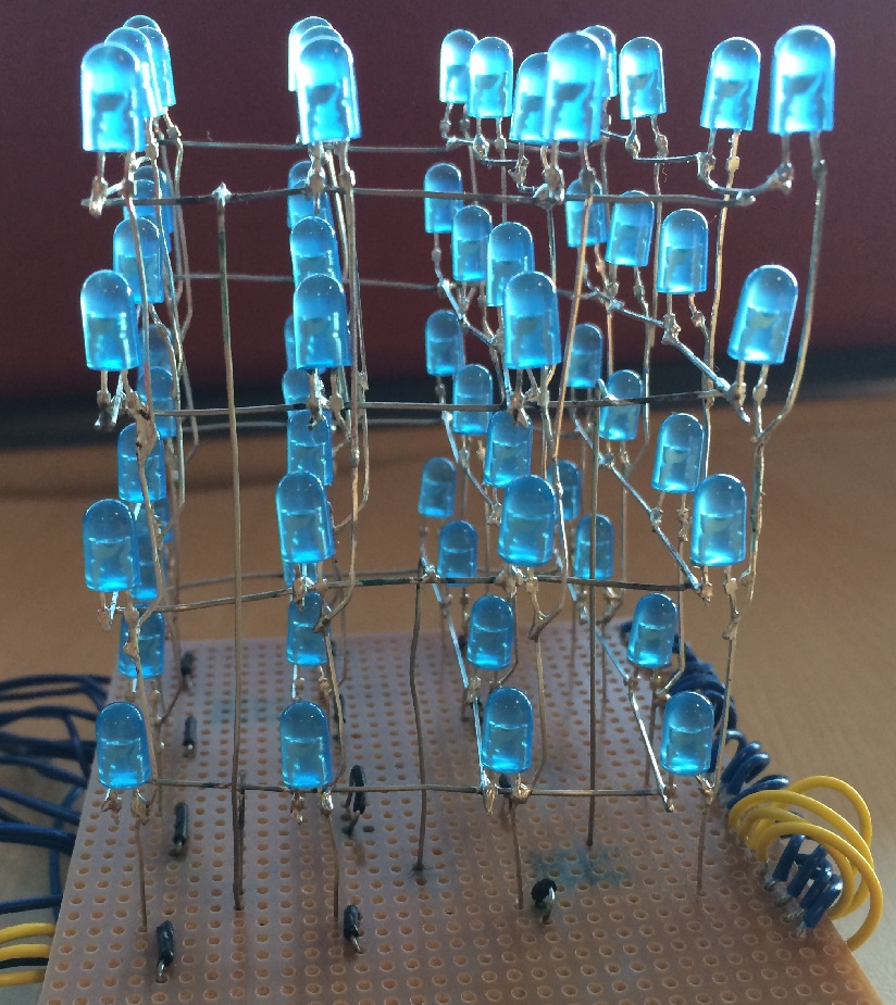
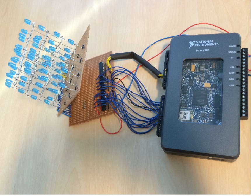
You must then use some solid core wire to connect the 4 cathodes to the connector A on the myRIO via a Darlington transistor array which will be able to connect them individually to ground. Then connect all the anodes to the connecter B on the myRIO via 2 buffers. The buffers amplify the current coming from the myRIO (3mA) to 20mA.

Software :
All the programming has been done in LabVIEW
The host communicates with the Real Time target (myRIO) via USB or wifi and the Real Time target communicates with the host via a FIFO. You will need three main Vis in your project, one for the host, one for the Real time target and one for the FPGA.
The host VI is the animation maker VI. Run this VI and then select which LEDs you want switched on or off in each layer for ecery frame. You can add several frames which when saved form the animation file. In the second loop on the block diagram a new file type is made which saves the animations. These files get saved into a folder and can then be dragged on to the myRIO to play.
The Real Time main Vi basically loads the files created by the animation maker VI, takes the content and puts it on to the FIFO which exists on the FPGA.
On the FPGA, the FPGA main Vi differentiates the running state , cancel state and idle state. Running state basically calls the FIFO , cancel state empties the FIFO and idle state runs continuously.
In order to run the program connect the myRIO to the host PC. Create an animation file using the animation maker VI. Copy this file and save it in a new folder called Animations on the myRIO in home:\lvuser so that it can be loaded while running the real time VI. Run the FPGA main vi then run the real time main vi and watch the animations you created earlier now playing on the cube!
Note : every layer has a common cathode which means that only one layer can be 'enabled' or lit up at once which creates major restrictions in performing advanced animations. The best solution is to put the theory of persistence of vision into practice.
We know that from this theory that the human eye will not be able to see individual frames as they change if they are changed at a rate greatr than 25 frames per second. Making use of this theory I decided to switch switch each layer on and off so quickly that the human eye cannot spot it and it appears as if all layers light up simultaneously, when in reality only one layer is lit up at one instance.
- Mark as Read
- Mark as New
- Bookmark
- Permalink
- Report to a Moderator
Hi
Can anyone give me the reference of the buffer used here
thank you 
