Phase-Locked Loop (PLL) on a myRIO
- Subscribe to RSS Feed
- Mark as New
- Mark as Read
- Bookmark
- Subscribe
- Printer Friendly Page
- Report to a Moderator
Code and Documents
Attachment
This is the program of a Phase-Locked Loop (PLL) implmented on a myRIO. A video goes with it
https://www.youtube.com/watch?v=IbvdBnNTRxg&feature=youtu.be
This is a tutorial showing how a PLL works and how to implement one on an NI FPGA device. I use a pure sine-wave VCO (since it is quite easy to do so) instead of a square-wave VCO. It uses a multiplier as a phase-detector and a first-order filter for the loop filter. The carrier frequency is low - 400Hz (for my application but the idea can be scaled up for more expensive applications) and I include the case of FM (in the video). The FM demodulated output is the filter output which includes residual 2f carrier feedthrough terms of 2X400=800Hz.
Instructions: Unzip the file and click on the project explorer file. You will need to search for your target myRIO (which will have a different name from mine). Then you need to copy the files across so that they are under your chosen target. This program only uses the FPGA and not the processor so there is only one .vi FPGA file.
You can see I have use connect C for the FM (or carrier) input AI0 and two outputs - the VCO output and the filter output use AO0 and AO1 - both on the C connector. Inject a sine wave of 400Hz (or you can change this but you must change the VCO free-running frequency to correspond). Look at the VCO output and see that it is lagging by 90 degrees when in lock. You can apply FM and take the output from the filter as the demodulated output.
Example code from the Example Code Exchange in the NI Community is licensed with the MIT license.
- Mark as Read
- Mark as New
- Bookmark
- Permalink
- Report to a Moderator
Dear tomnz,
I have given a try with your PLL-example and It works fine.
By investigating the example to learn more, I have replaced yours Butterworth filter with the 'similar' one from the Labview palette and the PLL stops to work!
Unfortunately, yours Butterworth filter is without block diagram.
Can you explain me what is under the hood of yours Butterworth filter and why the filter from the Labview palette doesn't work?
Regars,
Asper
P.S.: I use LabView 2014 SP1
- Mark as Read
- Mark as New
- Bookmark
- Permalink
- Report to a Moderator
I don't have the vi in front of me since it's at work and I am at home, but I had a quick glance at the video and I use only a first order filter I think which is not mine, only a vi from LabView (I will check Monday). If you use a second order you will lose a lot of phase-margin and possibly go unstable - the whole loop that is. it's all down to the Bode Plot of the loop like any control system. Where you put the cut-off frequency is also important of course. Make it too large and you let through lots of 2f carrier and make it too low and you lose bandwith and tracking ability. I have it at 40Hz. A rule of thumb is to put the unity-gain bandwidth of the loop at 2F carrier /10. So if you have a 100Hz carrier, make it at 2X100/10 = 20Hz.
- Mark as Read
- Mark as New
- Bookmark
- Permalink
- Report to a Moderator
Dear tomnz,
thanks alot for the reply.
I have used the Butterworth filter that comes with the FPGA Math & Analysis, that I have configurated as shown in the following image.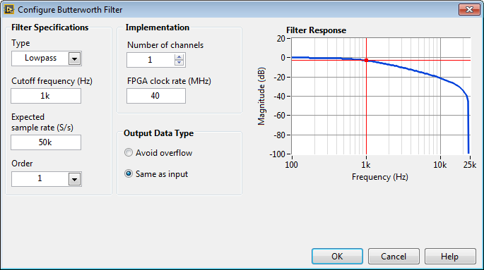
Is the filter correctly configured?
I have had a look to the filter VI with the 'Convert SubVI' function, and I have discovered that the filter shipped with LabView 2014 looks like different from that shipped with your example.
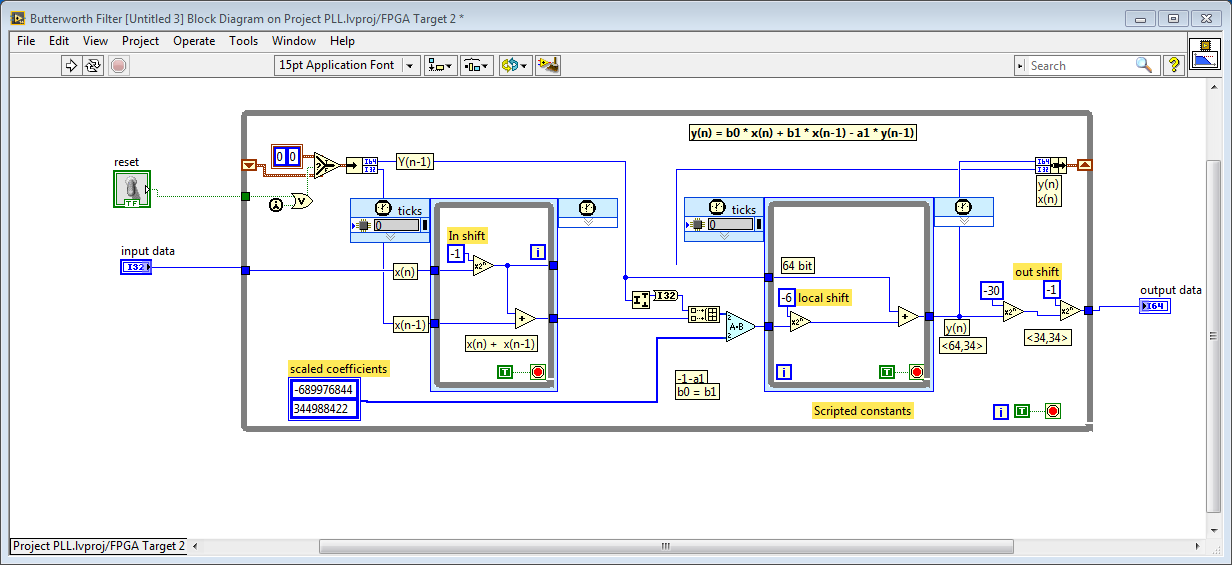
In the following images, the first image is the filter shipped with LabView 2014 and the second image is the filter shipped with your example.
LabView 2014 SP1:
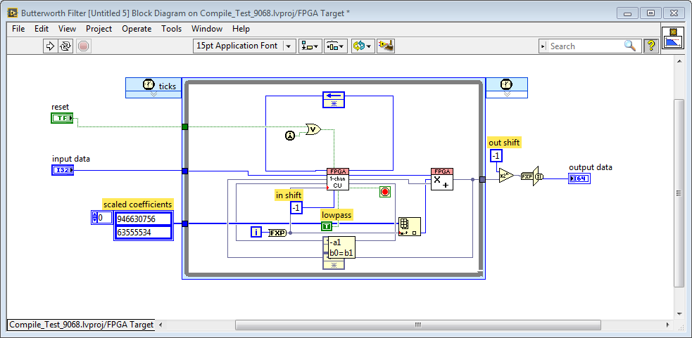
Your example:
Are the two VIs a different implementation of the same function? ...
Have you any idea why the filter shipped with LabView 2014 in the PLL implementation doesn't works at all?
Asper
- Mark as Read
- Mark as New
- Bookmark
- Permalink
- Report to a Moderator
This is interesting but I can assure you the filter vi is due to National Instruments and not my own one.
- Mark as Read
- Mark as New
- Bookmark
- Permalink
- Report to a Moderator
Probably NI has changed the filter design in the last labview releases.
The question is why one implementation works fine and the other does not works at all.
For instance, I have noticed that the 'scaled coefficients' are completely different, are those parameters filter-design dependent or can be one of the causes of the filter behaviour?
No idea,
😞
- Mark as Read
- Mark as New
- Bookmark
- Permalink
- Report to a Moderator
There could be perhaps an inversion or a greater phase shift. they don't show the phase shift and this is crucial. However a Butterworth should be the same for a particular cut-off.
- Mark as Read
- Mark as New
- Bookmark
- Permalink
- Report to a Moderator
I would test the filter on its own and check the phase
