Overview
This example demonstrates the principle of digital lock-in demodulation using LabVIEW. Using the principle of signal mixing, this example demonstrate how to find the envelope of a high frequency signal that is buried in a lot of noise.
Description
There are many situations in which scientists and engineers encounter situations in which they need to measure the strength of a signal over time. However, that signal is oscilating at a high frequency and is mixed with a lot of noise. These are the kinds of situations in which lock-in demodulation and filtering are useful.
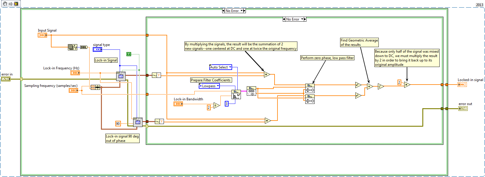
The principles behind lock-in demodulation are fairly simple. When two sinusoidal signals of the same frequency and phase are multiplied together, the result is a signal at twice the frequency as well as a 0 Hz component. This occurs because of the trigonometric identity:

Half of the signal shifts to the 0 Hz or DC range while the other half shifts to twice the original frequency. Then, a low-pass filter is applied and all of the noise and frequency-doubled signal are filtered out. All that is left is the "envelope" or the shape of the signal over time. The following image demonstrates how effectively the envelope of a signal can be extracted even amidst very strong noise.

Because we also want the result to be independent of the phase of the incoming signal, we multiply the incoming signal by two reference sine waves at the lock-in frequency. These reference signals are both 90 degrees out of phase. The filtered results of these two signals are combined as the square root of the sum of the squares of each.
Steps to Implement or Execute Code
- Open Lock-in example.vi . This is the main VI that calls the demodulator subVI
- Working parameters are already saved as default, so you should be able to run this immediately
- Experiment with different values for the frequencies, amplitudes, etc.
Requirements
Software
LabVIEW 2014
Hardware
Additional Images or Video