- Document History
- Subscribe to RSS Feed
- Mark as New
- Mark as Read
- Bookmark
- Subscribe
- Printer Friendly Page
- Report to a Moderator
- Subscribe to RSS Feed
- Mark as New
- Mark as Read
- Bookmark
- Subscribe
- Printer Friendly Page
- Report to a Moderator
Model Overview
This simple fuse SPICE model is uses typical parameters found in most datasheets:
- I2T melting integral
- Nominal resistance (under low current)
- Rated current
To appreciate the behavior and limitations of the model, it helps to study its internal structure, shown below:
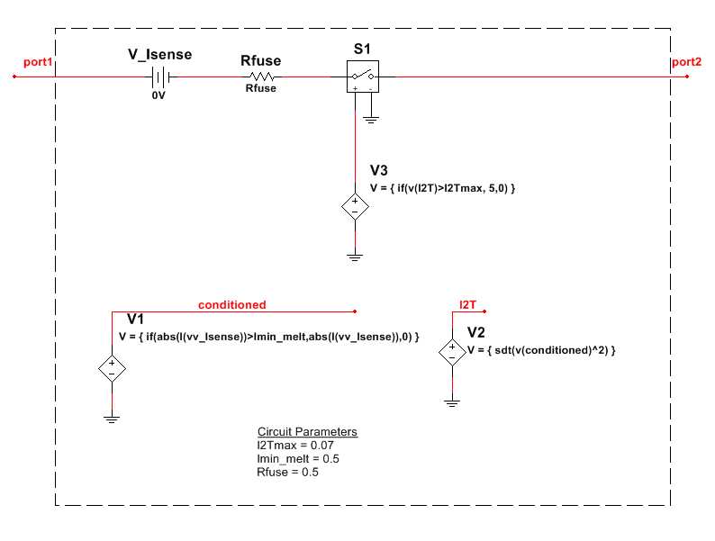
V_Isense is a 0V voltage source that acts as the current sensor, whose value is referenced by controlled voltage source V1. This source simply drives onto node conditioned the absolute value of the fuse current as an ideal voltage value, only if that current is greater than the minimum melting current value, Imin_melt. Otherwise, source V1 drives 0V on node conditioned. The minimum melting current value can be assumed to be reasonably close the rated current of the fuse part.
Controlled voltage source V2 uses the sdt() function to perform a running integral on the square of the voltage value on node condition, which we know represents the fuse current value. The result is placed on node I2T.
Finally, using the running integral value on node I2T, controlled voltage source V3 opens switch S1 if the value exceeds the melting point I2T value - the fuse is blown!
Discussion
One important attribute of this model is that it does not simulate any cooling behavior of the fuse after the minimum melting current is exceeded. Any excursions of fuse current above the minimum melting value are effectively integrated onto node I2T over the course of the entire simulation. Therefore this model can be valid only for one-time overload events. You will need to re-run the simulation for every overload event (unless of course the multiple overload events are very close in time such that the thermal cooling behavior in between those events is insignificant).
The model also does not model the increase in fuse resistance as it heats up.
A more detailed fuse model which models cooling and dynamic fuse resistance can be found here:
However, this more detailed model requires the user to obtain parameters which may not be readily available on datasheets.
Attachments
FuseComponent.ms13 contains the model implemented using a single Multisim component with a raw SPICE model. The component can be saved to the Multisim User database.
FuseSubcircuit.ms13 contains the model implemented using a Multisim schematic Subcircuit. The internal structure can be easily inspected in a graphical manner.
National Instruments
