- Document History
- Subscribe to RSS Feed
- Mark as New
- Mark as Read
- Bookmark
- Subscribe
- Printer Friendly Page
- Report to a Moderator
- Subscribe to RSS Feed
- Mark as New
- Mark as Read
- Bookmark
- Subscribe
- Printer Friendly Page
- Report to a Moderator
myBall&Beam
myBall & Beam is my take on a classical control system using the myRIO as the basis of the controller. Ball balancing systems are commonly found in universities labs, as an engaging tool to teach fundamental control theory to students. This type of system is an example of an open loop unstable system which is a common control problem in industry. myBall & Beam has been designed to allow people to have practical experience with a real-world control system and to show how this can be implemented using LabVIEW.
myBall & Beam works by controling the position of an ball on a beam by using an IR sensor to continuiously detect the ball's current position and a servo to control the tilt of the beam. This information is analysed on the myRIO's embedded processor and an appropriate control algorithm is run to provide feedback to the system. myBall & Beam has been programmed to run a PID (proportional integral derivative) algorithm to provide feedback to the system. PID is a common control algorithm used in industry that works well for single input single output systems (SISO). Of course, control software (develoepd in LabVIEW) could be easily modified to impliment more advanced control stragegies such as LQR if required.

Figure 1: Side View of myBall & Beam
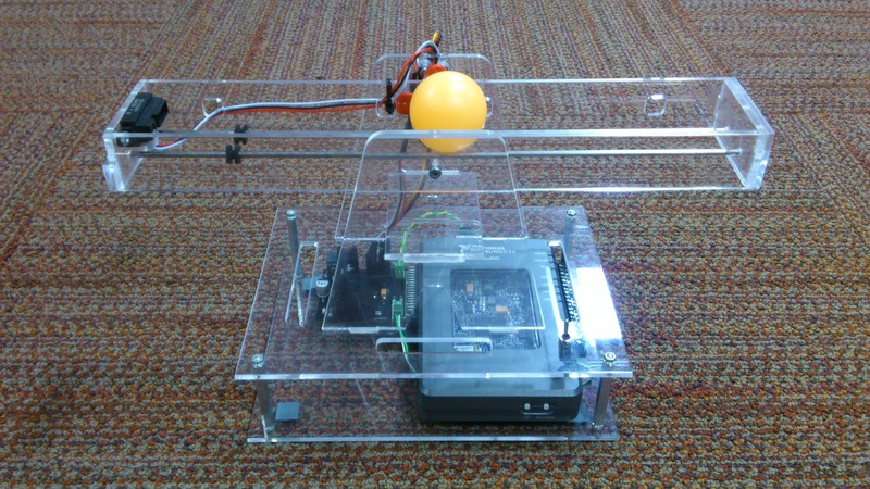
Figure 2: Front View of myBall & Beam
The software has been designed to allow the user to set the desired position of the ball (the set-point) and to dynamically adjust the PID control parameters. The ability to experiment with the control values on-the-fly brings learning control theory to life.
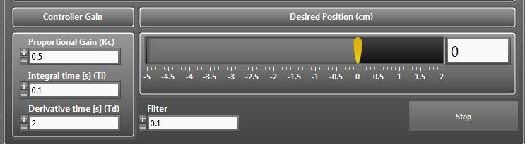
Figure 3: A clean user interface enables simple interactions with the control system
Additionally, the system has developed to be scalable to allow users to add their own control algorithms and see their effects on an actual system. The control algorithm and calibration VI's run on the myRIO and are interfaced with a host PC to change their parameters.
The overall design also includes a custom PCB to filter the signals and to power the myRIO, servo and IR sensor. The circuit was designed using Multisim and was exported to Ultiboard to design the PCB. THe aim of using a PCB for this system was for ease of use.
myBall & Beam Software

Figure 4: Front Panel of User Interface (UI)
The myBall & Beam software incorporates 3 modes of opperation
- Test Servo: Allows the user to control the position of the balancing beam, by moving the motor
- Test IR Sensor: Aquires and visualises data from the IR sensor, which monitors the position of the ball
- Start Ball and Beam: Uses the control algorithm to automatically position the ball at the desired set-point
The software was developed using LabVIEW's prebuilt library of control functions. This was suplimented by some custom functionality, which performs easing on the servo motor to facilitate smoother motion.
The myBall & Beam source code (including the host UI and the myRIO control application) is attached at the bottom of the page.

Figure 5: Block Diagram of User Interface (running on a host desktop/laptop)
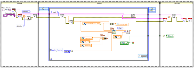
Figure 6: Block Diagram of PID Controller (running on the myRIO embedded processor)
myBall & Beam Circuit
I designed a custom circuit that plugs directly into the myRIOs MXP A connector using Multisim to create the circuit diagram and Ultiboard to design the PCB. The aim of the circuit was to reroute the signals between the IR sensor, servo and myRIO to ease setting up the system. The circuit also features a simple low pass filter at the output of the IR sensor to remove high frequency noise from the signal. Figure 7 and 8 show the circuit diagram, Ultiboard PCB design and the final PCB after manufacturing.
The myBall & Beam circuit files (including the multisim circuit design and the ultiboard files ready for fabrication) are attached at the bottom of the page.
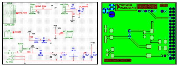
Figure 7: Multisim circuit diagram and Ultiboard PCB design

Figure 8: PCB prior soldering components to the board
myBall & Beam CAD
The physical build of the control experiment was designed using VariCAD, before being fabricated using perspex at the mechanical workshop of the University of Manchester. Figure 9 shows an explosion diagram of the CAD design.
The myBall & Beam CAD files are attached at the bottom of the page.
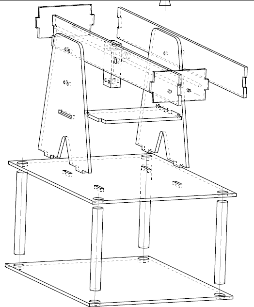
Figure 9: Explosion diagram of the myBall & Beam mechanical build
Steps to Execute Code
The system has been programmed to be easy to use so to run the program. As such it uses a RT Startup exe on the myRIO and an executable on the host PC. To run the program, please follow the following steps:
Skip to step 3 if you have previously set the RT Startup exe to run as startup.
- Connect the myRIO to your host PC and open myBall & Beam.lvproj.
- Expand the RT target (myRIO-1900) > Build Secifications > Right click on My Real-Time Application and select Run as Startup.
- Run the host executble from Ball & Beam Code 2013 > builds > Ball&Beam.exe or by right clicking the Ball&Beam.exe within the Project Explorer and selecting Run.
- From the User Interface of the executable, select the program you want to run. The options include the following:
- Test Servo.
- Test IR sensor.
- Run ball and beam control system.
Requirements
Software
LabVIEW 2013 for myRIO Module, LabVIEW 2013 PID and Fuzzy Logic Toolkit, Circuit Design Suite (Multisim & Ultiboard)
Hardware
myRIO 1900, Hitec HS-225 BB Mighty Min HT, Sharp GP2Y0A41SK0F IR Range sensor
About the Developer
I am an Electrical and Electronic Engineering student from the University of Manchester and am currently doing an internship with National Instruments. As part of my internship, I completed this project over the course of 2 weeks to demonstrate the ease of developing systems using NI technologies. I am also an avid LabVIEW programmer and a Certified LabVIEW Developer (CLD).
Additional Resources
Learn more about LabVIEW - ni.com/labview
Learn more about myRIO - ni.com/myrio
Evaluate myRIO: Request an evaluation unit - ni.com/myrio/evaluate
- Mark as Read
- Mark as New
- Bookmark
- Permalink
- Report to a Moderator
i need more details about the hardware of the actuator, and the IR.
Thanks in advance.
Ariel
- Mark as Read
- Mark as New
- Bookmark
- Permalink
- Report to a Moderator
Hi Ariel,
For the sensor and actuator, I used the following hardware.
Sensor: Sharp GP2Y0A41SK0F IR Range sensor
Servo: Hitec HS-225 BB Mighty Min HT
Thank you.
Kind regards,
Nigel
- Mark as Read
- Mark as New
- Bookmark
- Permalink
- Report to a Moderator
hello Aegiloru,
I use the version of LabVIEW 2014, despite compiling works after crashes on the main page.
You could kindly help me.
thank you
