- Document History
- Subscribe to RSS Feed
- Mark as New
- Mark as Read
- Bookmark
- Subscribe
- Printer Friendly Page
- Report to a Moderator
- Subscribe to RSS Feed
- Mark as New
- Mark as Read
- Bookmark
- Subscribe
- Printer Friendly Page
- Report to a Moderator
myRoboLab: Custom design Robotic Arm
Overview.
myRoboLab is aimed for students and robot enthusiasts who would like to learn the basics about robotic arms in a fun and interactive way. It allows the user to visualise the motion and understand further the concept of kinematics either by using the three-degree of freedom robotic arm (designed from scratch) or by running the simulation on the PC. Both of these features are available to the user but they depend on the user's resources.
Background.
As the robotic arm has three degrees of freedom, it means that with the use of three servo motors it is able to move in a three dimensional space. Furthermore, with the use of an extra motor at the clamp it is also able to pick up objects.
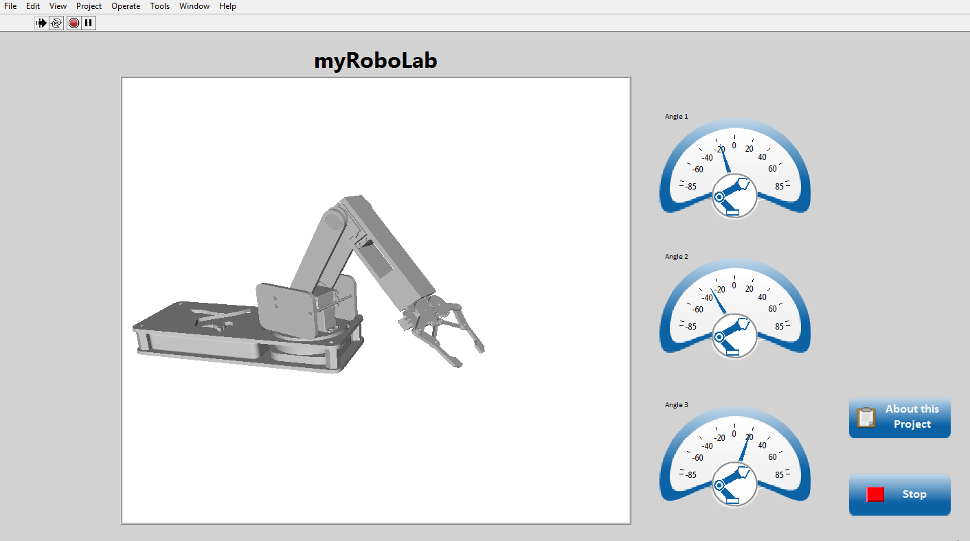
Figure 1. CAD simulation on computer. Take a look at the link below!
As not everyone will have access to the robotic arm, a simulation is also displayed on the screen moving simultaneously with the robotic arm in order to increase the amount of people who can benefit from this project. If you would like to learn more about the simulation (figure 1) please feel free to follow this page, https://decibel.ni.com/content/docs/DOC-41278, where you can find more information regarding the simulation.
This project was designed as part of my individual week-long project in my placement year, in order to facilitate learning for the robotics funs and help them to handle better the NI hardware and software in robotic applications.
If you would like to ask me any futher questions regarding the project or would like to provide me with feedback please feel free to do so at the bottom of the community page where you can also find more details about the project including the CAD files as well as the code.
Designed and Built
As mentioned earlier, the robotic arm used for this project was designed by myself specifically for this project. In figures 2 a-c below you can see screenshots of the CAD design as well as the actual mechanical built in figure 3 a-d. Since some of you may be interested in replicating this project, or even reuse my design in your own project, CAD files are also included at the bottom of the page.
For this project, lasercut acrylic parts were used by using the PDF drawings below, but a 3D printer can also be used depending on what you have available. When using a 3D printer you will need to find the solidwork parts and convert them to STL files. This can be done by opening any part, clicking "save as" and then chosing STL as the file format.


Figure 2 a-c. CAD design of the robotic arm used.

Figure 3 a-d. Robotic arm built.
Circuit.
For this project, no complex circuitry is required as all the motors require 5V; the motors are controlled by using the digital channels. Figure 4 shows below, that the myRIO 5V channel was not used, as the current that would be provided would not be high enough to power all the motors effectively. With the use of an UBEC and a separate power supply, enough power can be suppled to all the motors. UBEC is a 'switch mode' DC regulator that takes the high voltage (15V) from the power supply and converts it to a constant and safe 5V for the servos.
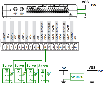 Figure 4. Wiring diagram.
Software.
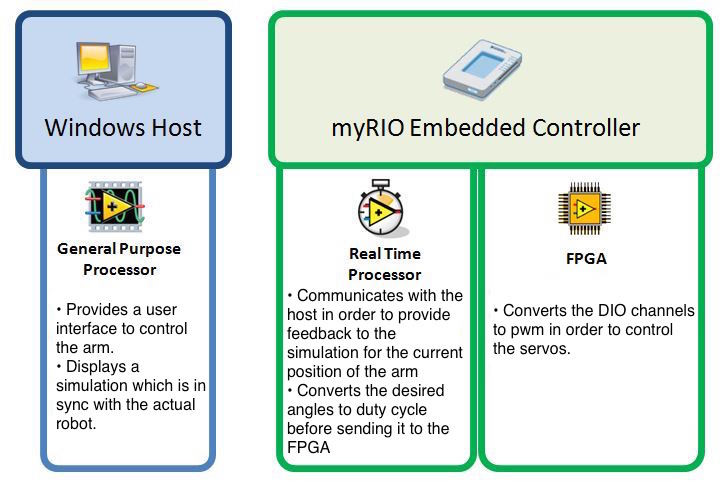
Figure 5. myRoboLab software
In figure 5 above, you are able to see more details on what the host computer, Real-Time and FPGA targets are responsible for. With the use of LabVIEW, all three targets can be programmed following the same intuitive graphical programming approach, but let's take a closer look at the program.
myRoboLab allows the user to select one of the three modes of opperation as it can be seen in the figure 6 a-c below.
1. Forward Kinematics
2. Inverse Kinematics
3. Trajectory Planning

Figure 6 a-c. Front panel screenshots.
Of course, as this was a week-long project, the aim was to get all three operations working, but sometimes not everything can go as planned. As a result, choosing an appropriate architecture would allow for the code to be modular and expandable. Since for this project the robot has to behave differently depending on the mode of operation, the QMH (Queued Message Handler) architecture was the best to use. If you would like to learn more about LabVIEW architectures, including QMH, please take a look at the following link https://decibel.ni.com/content/docs/DOC-22047.
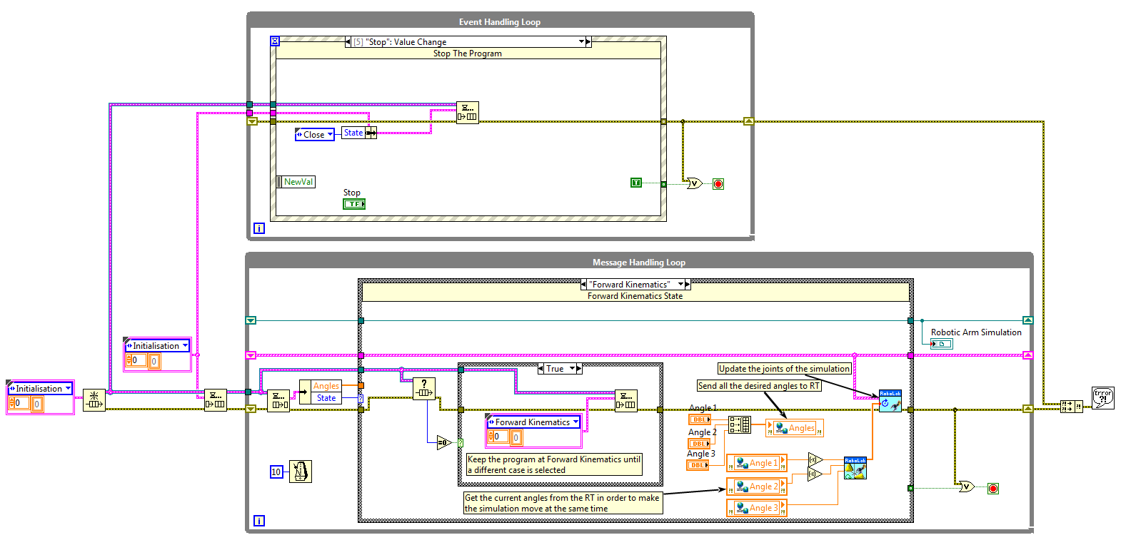 Figure 7. Block diagram screenshot.
Kinematics.
Since not everyone reading this page has a background in robotics, lets take a better look at what the three modes of opperation mean:
Forward Kinematics:
Forward kinematics refers to the use of the kinematic equations of a robot to compute the position of the end-effector from specified values for the joint parameters, in this case being the position of the servo motors. Below you can see in figure 8 a sketch of the robotic arm and the Denavit-Hartenberg parameters. Furthermore, you can also see the forward kinematic equations derived for the robotic arm. Although at the end a different approach was followed that did not require the Matrix, it might be useful to people who would like to replicate the system with a different approach. Please note that C corresponds to cos and S to sin as the equation had to fit inside this page and still be readable.
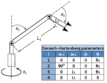
Figure 8. Forward Kinematics.
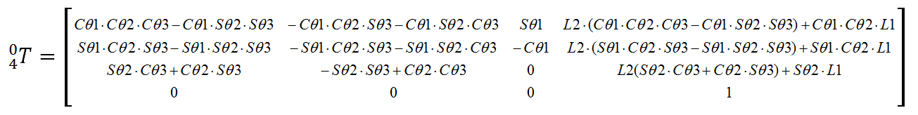
Figure 9. Forward Kinematics equation.
Inverse Kinematics:
Inverse Kinemtaics refers to the use of the kinematic equations of a robot to determine the joint parameters that provide a desired position of the end-effector. Below you can see the formulas derived for the Robotic arm, as well as a figure with the variables used in the equations.
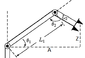
Figure 10. Inverse Kinematics.
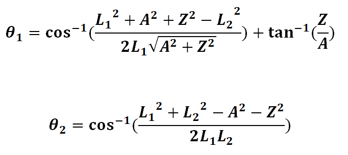
Figure 11. Inverse Kinematics equation.
Trajectory:
Trajectory planning refers to moving the manipulator arm from an initial position to a desired position through an intermediate point, usually for obstacle avoidance.
About the developer:
My name is Menelaos Kanakis and I am a student at the University of Leeds specializing in Mechanical Engineering. I always had a passion for robotics and the way they can be used to assist our every day lives, but I never had enough time during term time to learn about it. During my 12 month internship at National Instruments I took advantage of my time and the high capabilities of the National Instuments hardware and software to design, build and program the robotic arm seen above for my individual week-long project.
Attachments:
myRoboLab Code:
Complete LabVIEW code.
CAD Drawings:
CAD drawings for laser cutting.
CAD Files:
CAD files designed in SolidWorks. These can be used also for 3D printning the robotic arm.
- Mark as Read
- Mark as New
- Bookmark
- Permalink
- Report to a Moderator
Cool project bro
Applications Engineer
National Instruments
- Mark as Read
- Mark as New
- Bookmark
- Permalink
- Report to a Moderator
kudos 
- Mark as Read
- Mark as New
- Bookmark
- Permalink
- Report to a Moderator
Thank you very much nolsqn! The page should be completed soon if you would like to visit again and see the new video demonstrating the functionality better
- Mark as Read
- Mark as New
- Bookmark
- Permalink
- Report to a Moderator
Impressive project Menelaos, we need to make sure we make the most of your skills when you come back to Leeds for your 3rd year. This looks like it would make a great start to a level 3 project !!
- Mark as Read
- Mark as New
- Bookmark
- Permalink
- Report to a Moderator
Thank you very much for your good words. I am really looking forward to next years project!
- Mark as Read
- Mark as New
- Bookmark
- Permalink
- Report to a Moderator
Massive congrats Menelaos! It is impressive that you created the whole mechanical design, programmed the robotic arm and also created the 3D simulation (which works great on my computer). It is a truly integrated project. Even though it's a complex program, the code is clean, has lots of subVIs and is well commented. Really love the video too, it explains the project clearly!
- Mark as Read
- Mark as New
- Bookmark
- Permalink
- Report to a Moderator
I would like to thank you very much for your good words Petru. It means a lot to me that an amazing engineer and LabVIEW user like yourself liked the project I worked on.
- Mark as Read
- Mark as New
- Bookmark
- Permalink
- Report to a Moderator
I just saw this project!
Great job Menelaos. I'm really impressed!
- Mark as Read
- Mark as New
- Bookmark
- Permalink
- Report to a Moderator
This is an amazing job! There's an incredibly bright future ahead of you Menelaos.
- Mark as Read
- Mark as New
- Bookmark
- Permalink
- Report to a Moderator
This project can really help me a lot.
thank you very much
—regards
- Mark as Read
- Mark as New
- Bookmark
- Permalink
- Report to a Moderator
Can you share the forward and inverse kinematic solution please?
