- Subscribe to RSS Feed
- Mark Topic as New
- Mark Topic as Read
- Float this Topic for Current User
- Bookmark
- Subscribe
- Mute
- Printer Friendly Page
Getting Started With Channel Wires
04-02-2015 10:15 AM
- Mark as New
- Bookmark
- Subscribe
- Mute
- Subscribe to RSS Feed
- Permalink
- Report to a Moderator
The basic description of channels here is still correct, but many details have changed between the limited release in LV 2015 and the official release in LV 2016.
For LV 2016, the best place to Get Started is to look at one particular shipping example:
examples\Channels\Basics\Channel Basics.lvproj
This will give you a full step-by-step tutorial for Channel Wires. Then you can explore the other examples to learn more.
Intro
In 2006, the NIWeek keynote showed off an idea called "asynchronous wires". Today, we have a working version of those wires that we aren't quite ready to productize, but we are ready to show to a wider audience. Now called "channel wires", these entities allow one loop to communicate information to another loop running in parallel. It is like having a queue or a variable that one loop writes into and the other loop reads from, but instead of using a refnum or a named variable, the data transfer can be represented graphically as a wire. This provides the communication channel with fewer nodes than the refnum case (no worrying about creating and destroying it) and with more awareness of where data is going than the variable (you can see all the places the wire connects into). Depending upon configuration, these wires are capable of expressing pipelining, circular dependencies between running processes and communication into asynchronusly called VIs.
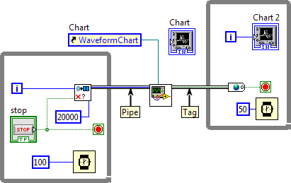
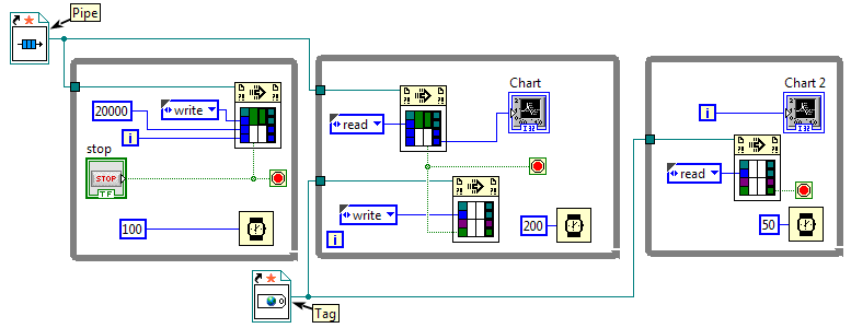
In the image below, you can see two types of channels. The top channel is a pipe. It behaves like a queue -- values go in on one side and are buffered and come out on the other side in the same order they went in (FIFO order). The bottom channel is a tag. It behaves like a variable. There is only one value, and the reader reads whatever value was last written.
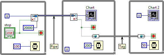
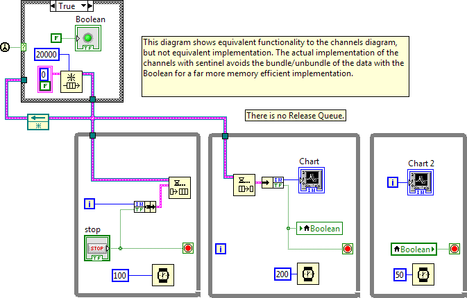
Channels do not do anything that you couldn't already do with existing LabVIEW functionality. They are, in fact, written with G code -- if no channel has the communications features that you want, you can create your own new one! The value of channels is that they provide a visual record of where data is flowing in an application. For static communications, they may be easier to document and to debug. The code above is functionally equivalent to this:
Are Channels Really A Supported LabVIEW Feature?
Channels ship as part of LabVIEW 2015, but they are not officially released. They have been tested and made resilient but have not been polished to the degree of officially released features. A big reason for this is that NI is not sure if they are a good idea in their current form. We want to hear feedback from users about UI, functionality, performance, etc. The best way to do this was to make them available to users who want to try them out without encouraging users generally to adopt them.
National Instruments will continue to support code written with the channels in future LabVIEW versions. If you use them in your code, we will make sure that there is a way to upgrade your code from LabVIEW 2015 to LabVIEW 2016 and beyond. This may require some minor manual edits or running a scripting VI as opposed to our ususal goal of automatic mutation. We will make sure that the code you write today can be upgraded, we just may need more wiggle room than usual depending upon the feedback we get from users.
If you contact National Instruments with a bug report, most Application Engineers will not have heard of channels. To get support about an application that uses channels but where your problem is not related to the channels, you may have to explain to the AE what they are and then talk about the real issue. To get support on channels themselves, please post bug reports RELATED TO CHANNELS to this forum. R&D will be monitoring this forum more directly than we monitor most other user forums. Attempts to use this forum to escalate other LV or NI related issues will get moved to other forums. You may also wish to check the Channel Known Issues page.
Enabling Channels In Your LabVIEW
Channels ship with LV 2015 but are not initially exposed in the interface. To get started with channel wires, you need to turn them on in LV 2015. To do this, open and run this VI:
<labview 2015>\resource\ChannelPopupMenuItems\InstallChannelPopupMenuItems.vi
(Use the same relative path on Mac and Linux.)
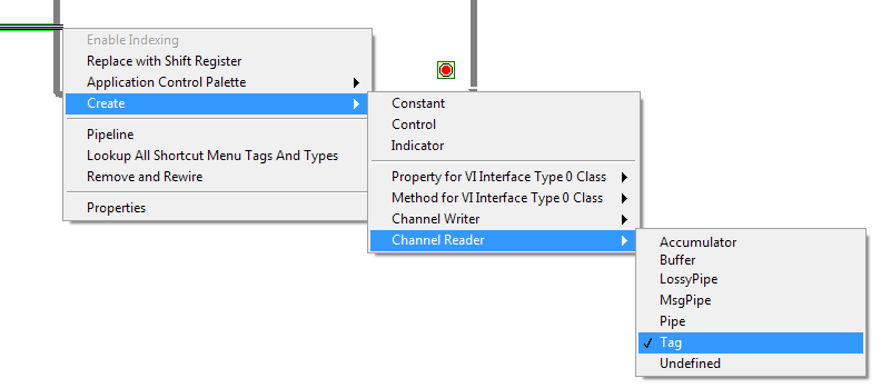
After running this VI, you will now see new menu items in the Create submenu when you popup on most terminals.
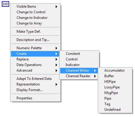
The Channel Writer menu creates write nodes; The Channel Reader menu creates read nodes. Each of the items in the list is a different channel template with different performance characteristics and user contracts. One of the things we would like feedback on from users of LV 2015 is which of these templates is most useful to you, which ones need different default configurations, etc. Each template is replicated on disk to carry the specific data type of the terminal that you used to create it.
Once you have an endpoint on your diagram, you can right click on it to configure it. The configuration options are in the Replace submenu. First, with Replace >> Channel, you can replace one template of channel endpoint with another template. The checkmark shows the current channel template.
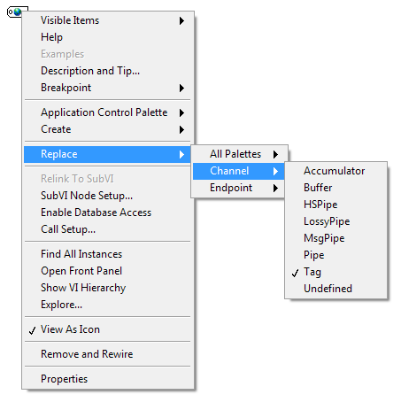
The Replace >> Endpoint submenu lets you choose the endpoint style. Each of the channel templates may have multiple endpoint styles. When the template is instantiated, all the endpoint styles are available for you to use. The Tag template, for example, has four endpoint styles. We can create more in the future as needed. Feedback from users on the styles is appreciated.

You create the Read endpoint in essentially the same way but start by right-clicking on a channel wire attached to the border of the structure node where you want the reading to occur. The checked item shows the type of the channel wire to make it easy to identify which endpoint matches the channel wire. After creation, you can Replace the Read endpoint with a different version if you choose.
Forkable vs. Non-Forkable Channels
Some channels allow you to fork the channel wire to have multiple writers and/or multiple readers. Other channels will result in a broken block diagram if you attempt to fork the wire. The templates that have "Pipe" in their name are non-forkable (except MsgPipe which I hope we rename in the future). All the others can be forked. Pipes guarantee single writer and single reader. With that guarantee in place, they are often able to achieve more efficient code, but, more importantly, when you make a pipe part of your infastructure, you are documenting the intended use of your channel and guaranteeing that no other module is injecting or stealing values from your channel.
Debugging: A Special Kind Of Probe
If you probe a channel wire the way you are used to doing with most wires, you'll get a VI refnum probe. This will mostly be useless. If it updates (and it is easy to miss the update), you'll get a one-time snapshot of the refnum value, not the ongoing state of the channel.
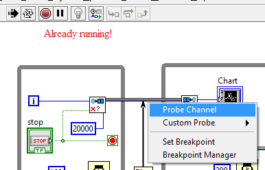
The existing debug solution for channels is to start your VI running and then right click on the channel wire and choose "Probe Channel". It won't work if you try to probe before the VI starts running, but after it starts running, you can probe anywhere along the channel wire, even segments that, if they were regular dataflow wires, would have already executed.
The "Probe Channel" menu item will instantiate a probe VI that will update and stay up-to-date as data is written into and read out of the channel.
Unfortunately, not all of the channel templates supports probing. The HSPipe, for example, does not support probing because supporting probes was creating a noticeable slowdown. R&D will continue to work on improving this situation.
Channels CAN Connect To SubVIs and (Asynchronous) Call By Reference Nodes
Channels are not restricted to just the local diagram. Both of the following are legal.
Pass into/out of subVI:
Pass into/out of Call By Reference:
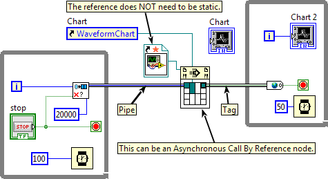
Utility VIs for filtering, replicating, or merging channels generally need to be reentrant. These VIs generally have a While Loop on their diagram such that they will run as long as the application runs, so they never return. If they are not reentrant and there is more than one caller, one of those callers is going to hang.
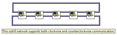
Channels Can Create Cycles
Channels do allow for bidirectional communication as well as any more complex cyclic graph that you would like to construct.
The Green Background
You may notice that sometimes the channel wire has a green background. To see this, your LabVIEW configuration file (labview.ini if you are on Windows) needs to include this setting:
asynchWiresEnabled=2
(case sensitive on case sensitive platforms)
This is a debug mode for those of us in R&D, but it may be helpful for some of you trying to understand how channels work.
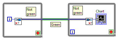
In any VI hierarchy that is not broken, there will be one segment of a channel wire that has a green background. This segment is the "top" segment, meaning if you were to trace the wire using "step out" from the write endpoint and using "step out" from the read endpoint, this is the segment that is on the diagram common to both. For any channel wire, such a diagram always exists. It may not be in the same subVI as the endpoints, as you can see in the earlier sections where the channel wires enter subVIs.
Creating Your Own Channel Templates
We created channels with the aim of being able to express any fixed communication between two pieces of code within the same application instance (we have longer term plans to extend to cross-target communication). But having the ability to express that communication does not mean that the shipping templates actually cover all the communications needs users may have. It is probably impossible for National Instruments to ship templates to cover every use case. For this reason, we have made the system extensible using G code.
To create your own template...
1. Go to this directory:
<labview 2015>\resource\Channels\
(Use the same relative path on Mac and Linux.)
Please ignore the subdirectories that start with an underscore -- those are either remnants of an earlier implementation of the channels that we did not get around to removing before shipping LV 2015 or utility VIs used by the internals of the feature.
The other subdirectories contain one template each. Pick the template subdirectory that is closest to the one you want to write. Remember that Pipes will not be forkable and non-Pipes will be forkable. That's the biggest thing to remember when choosing your starting point. (If this becomes a publicly released feature, I would hope we could provide a scripting wizard to help with this process.)
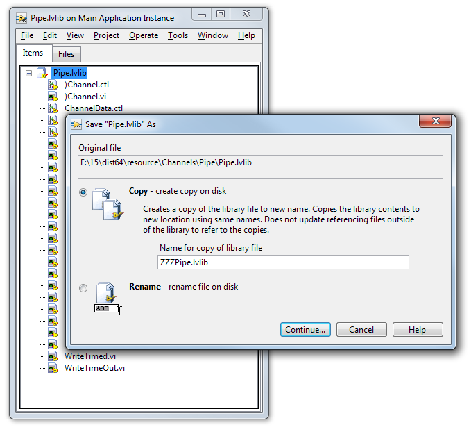
2. Inside your chosen subdirectory there is a .lvlib file. Open that file in LabVIEW.
3. Use File >> Save As >> Copy to create a duplicate of the library and all of its member VIs. Save it to a new directory next to the existing templates.
4. (optional) Even without making any further changes, your new channel is now available in the right click menus. Right-click on a terminal to verify that you see your new library listed in the Create menu.
5. Using Save As >> Copy will create a new copy on disk but does not open it in memory. So now open your new .lvlib file.
6. Edit the member VIs to do what you want to do. NOTE: The right-click menu items that make channels work are particularly sensitive to the names of the terminals. This is not a necessary restriction, but one that we didn't fix yet. So for 2015 at least, try to use terminal names that are the same as existing channels.
That's it! ... what? OH... you want more information about what to do in step #6? Ok... 🙂
What Goes On Behind The Scenes
Consider the first example of channels shown at the top of this page. What is shown below is a rough version of how the compiler sees the code. The endpoints, both read and write, are inlined into the caller. The contents of those diagrams are, essentially, shared VI refnums to a single instance of a reentrant subVI. That core VI contains all of the state needed to drive the channel.
This glosses over a number of other aspects of compiling channels, but this is how all the channels work at their heart -- the channel wire is replaced by a static VI reference to a clone VI that both writers and readers share.
Some of the implementations use the core VI for their entire implementation. Take a look at the Pipe template for an example of one of these. Other implementations use the core VI just to get started and thereafter use some entirely different refnum. See the HSPipe template for an example. In the Pipe template, the core VI is called every time a read or write endpoint executes. In the HSPipe template, the core VI is called only once to share a standard queue refnum between the two endpoints; thereafter, every call to the endpoints just uses the queue primitives.
The Parts Of A Channel Definition Library
a. The two files that start with ) character [REQUIRED]
In the library, there are two special members whose file names start with a close parentheses -- one .ctl and one .vi.
a1. The )*.ctl
This will be the typedef that actually defines the channel wire itself on user diagrams. When you run a channel into a subVI, the terminal of the subVI will be of this type.
You should not modify that .ctl except to change its icon. If it starts with a single ) then this is a wire that is NOT forkable. If it starts with a double )) then it is a wire that IS forkable.
Feedback is requested for how users would prefer to identify this special typedef and its configuration. For a long list of reasons, R&D strongly prefers that we encode the specialness in the name of the file rather than as an attribute of the file which translates to an attribute on the type. The close parentheses has been a special reserved name in LabVIEW since LabVIEW 8.5 without causing problems for any users, so we are confident that such a naming convention would not suddenly break existing user code, but it is somewhat cryptic. We are open to discussions of better options.
a2. The )*.vi aka "the core VI"
This is the core VI where the implementation of your channel typically resides. It MUST be a preallocated reentrant VI. It will store any state that is going to be shared between the writer(s) and reader(s).
This VI MUST have the SAME file name as the .ctl file other than the file extension. The connector pane of this VI is quite flexible. The only terminals that must exist are the "channel in" and "channel out" terminals. If you change the VI connector pane, make sure you update the FP controls of Instantiate.vi (see below).
This VI is called "the core VI" in comments below.
b. Instantiate.vi [REQUIRED]
This is the VI that will generate the VI refnum that will be shared between the write and read endpoints. You can put code into this VI, but most of the time it just returns a static VI reference.
The connector pane of this VI is strange. It has both an input and an output, but only the output is ever wired. Do not delete the input and do not wire the input. If you delete or wire the input FP terminal, the compiler will not handle your channel correctly. This idiosyncracy is something we will investigate cleaning up if channels are made into a public feature.
=== all remaining member VIs are optional ===
c. Element.ctl
This is a typedef that is always a variant. Do not change it. When the template is instantiated for a particular data type, this typedef will be changed to be the type of the data to carry. If your channel does not change its data type (for example, the Message Pipe) then you do not need an Element.ctl.
d. Write______.vi
Any VI whose file name starts with "Write" will be displayed in the shortcut menu for write endpoints. Generally these VIs should be marked as "inline" in VI Properties and will make a call to the channel's core VI. Sometimes one of these endpoint VIs will just be a wrapper around another endpoint VI.
At the moment the shortcut menus do not use the display name of these VIs. This will be fixed in future releases.
e. Read______.vi
Any VI whose file name starts with "Read" will be displayed in the shortcut menu for read endpoints. Generally these VIs should be marked as "inline" in VI Properties and will make a call to the channel's core VI. Sometimes one of these endpoint VIs will just be a wrapper around another endpoint VI.
At the moment the shortcut menus do not use the display name of these VIs. This will be fixed in future releases.
f. Probe.vi
Name a reentrant VI "Probe.vi" to use it as a custom probe for your asynch wire when the user chooses "Probe Channel", as described above. You will need to include a call to Probe.vi in your core VI to update it. See the Pipe template for an example.
g. Init.vi
Delete this VI from your template. It is cruft left over from development that should have been deleted before LV 2015 shipped.
h. Other VIs that you see in a template
h1. You can have VIs that are just subVIs to support the above functions. "Grow.vi" in the Pipe template is an example of such.
h2. You can have VIs that your users might choose to call. An example is "Replicate2.vi" in the Pipe template. This VI takes a single incoming pipe and duplicates its contents into two separate outgoing pipes.
You are free to add or remove VIs from the channel library as needed.
Conclusion
This implementation of channels has some rough edges in the editor, but it is robust for its run time behaviors. Before R&D puts further effort into improving the developer experience, we would like to know if these are useful. We would like to know what sort of editor gestures would make them user friendly. This feedback will help us tune this feature for some future public release.
Thank you.
11-24-2015 07:46 AM
- Mark as New
- Bookmark
- Subscribe
- Mute
- Subscribe to RSS Feed
- Permalink
- Report to a Moderator
I like the idea of channel wires. We did something similar a few years ago. But this approach is much easier to use. Poster presented on ICALEPS in 2003: http://www.researchgate.net/publication/242705141_THE_PHELIX_CONTROL_SYSTEM_BASED_ON_UML_DESIGN_LEVE.... This was a feasibility study based on ObjectVIEW, but not adopted by the responsible control system developer. Within the diploma thesis of A. Schwinn distributed Object- and Petri-Networks (August 2007) were implemented within the CS Framework, https://www-alt.gsi.de/documents/DOC-2007-Aug-64-1.pdf and https://wiki.gsi.de/foswiki/bin/view/CSframework/WebHome. Holger
11-24-2015 09:22 AM
- Mark as New
- Bookmark
- Subscribe
- Mute
- Subscribe to RSS Feed
- Permalink
- Report to a Moderator
Thanks for the feedback, Holger. Your first link seems to be broken -- there's no document loaded in the web page.
11-24-2015 09:35 AM
- Mark as New
- Bookmark
- Subscribe
- Mute
- Subscribe to RSS Feed
- Permalink
- Report to a Moderator
I tried IE and Firefox, both time the document on researchgate is shown. Maybe you need to click somewhere on the page to display the full text.
11-24-2015 11:39 AM
- Mark as New
- Bookmark
- Subscribe
- Mute
- Subscribe to RSS Feed
- Permalink
- Report to a Moderator
Try following link. I think this was the original one.
http://accelconf.web.cern.ch/Accelconf/ica03/PAPERS/WP549.PDF
Sorry for confusion. Holger
11-24-2015 05:00 PM
- Mark as New
- Bookmark
- Subscribe
- Mute
- Subscribe to RSS Feed
- Permalink
- Report to a Moderator
It loaded in Safari for me. It has some sort of flash wrapper so that might not work if one has done a reasonable thing and gotten rid of flash.
12-08-2015 01:30 PM
- Mark as New
- Bookmark
- Subscribe
- Mute
- Subscribe to RSS Feed
- Permalink
- Report to a Moderator
I will really like to follow this document but I cannot understand what is going on because many of the functions do not have their labels turned on. My thought would be to turn on all the labels in something that is going to be presented as new ideas to people who simply will not recognize some of the 10,000 or more function icons used by LabVIEW. Is there an actual policy against showing label names?
12-08-2015 01:56 PM
- Mark as New
- Bookmark
- Subscribe
- Mute
- Subscribe to RSS Feed
- Permalink
- Report to a Moderator
I don't see any definitions of the various templates that would allow me to choose the one I need. Is this supposed to be obvious from going through all the VIs in the associated Channels folder or is there some other document that describes the functionality of the templates?
03-31-2017 01:05 PM - edited 03-31-2017 01:06 PM
- Mark as New
- Bookmark
- Subscribe
- Mute
- Subscribe to RSS Feed
- Permalink
- Report to a Moderator
can I back-save to 2015 from code in 2016?
Is there any way to include the Extra files in the source code folder?
Ben
03-31-2017 01:19 PM
- Mark as New
- Bookmark
- Subscribe
- Mute
- Subscribe to RSS Feed
- Permalink
- Report to a Moderator
What is the recommended method for ensuring that channel wires stuff is backed up?
Since there a bunch of file scattered to support them, How do I get them into the source code folder so that they are included in SVN?
Ben
