- Subscribe to RSS Feed
- Mark Topic as New
- Mark Topic as Read
- Float this Topic for Current User
- Bookmark
- Subscribe
- Mute
- Printer Friendly Page
Correction of lens distortion for the Oculus Rift using LabVIEW
05-22-2015 11:31 AM
- Mark as New
- Bookmark
- Subscribe
- Mute
- Subscribe to RSS Feed
- Permalink
- Report to a Moderator
Overview
In document https://decibel.ni.com/content/docs/DOC-42169, it was shown that the LabVIEW 3D picture tools can be used to generate stereo images onto the Oculus Rift. Good rendering rates were obtained and a demonstration executable is available. However, the developed application did not include corrections for chromatic and pin cushion distortions. In this document, a technique is presented to correct the images at least for the pin cushion distortion, but at the cost of reduced rendering rates and resolutions.
Do not hesitate to send me your comments or suggestions concerning the topics discussed in this document.
Oculus client distortion
The distortion corrections can be seamlessly taken care of by the Rift engine when using the Direct HMD Access mode, using either OpenGL or Direct3D rendering. However, in that mode, it is not possible to take advantage of the LabVIEW 3D picture tools. In the Extend Desktop mode, the Oculus Rift appears as an additional monitor in Windows and 3D images can be rendered in a window on this additional monitor. For this mode, and for cases where the programmer wants to have access to details of the distortion corrections, Oculus offers the client distortion.
In client distortion, the Oculus Rift provides two triangular meshes, one for each eye, and sets of texture coordinates for each mesh. The idea is to render images from the 3D picture controls corresponding to each eye. Each image is then used as texture on its corresponding mesh.
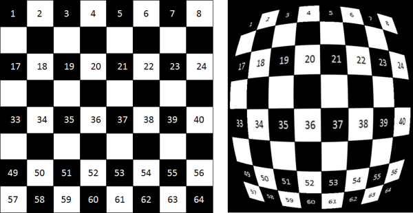
Either the meshes, the textures, or the rendered images must be adjusted for the desired aspect ratio. See one of the 2D meshes rendered as wireframe in a 3D picture tool in the figure below.

One of the meshes with an aspect ratio of 1 provided by the Oculus Rift SDK for client distortion.
The Oculus SDK provides the vertices of the meshes (only the X, Y components as Z is supposed to be constant), the vertex indices, and the texture coordinates. Three sets of texture coordinates per eye are available, one for each of the red, green, and blue color components to attempt to correct for chromatic aberrations. The meshes and texture coordinates take the characteristics of the lenses that are used and the specific parameters of the user as entered in the Oculus configuration utility.
Additionally, the SDK provides vignette factors, and time warp factors. The vignette factors can be used to reduce the sharp edges near the borders of the meshes. The time warp factor is used to help reduce apparent latency by modifying the texture to compensate for rapid head movements. The use of the vignette and time warp factors is not demonstrated here. The results shown here were obtained with the Oculus runtime versions 0.4.4.0, 0.5.0.1, and 0.6.0.0
Labview code
Using a DLL developed for communications between LabVIEW and the Oculus SDK, two coordinates are obtained, Z being set to 0, and two texture coordinates for each vertex of the meshes, and a series of indices giving the order of the vertices to form the triangles of the meshes. Below is shown the LabVIEW code to produce one of the mesh and how the texture coordinates are applied to the mesh. The aspect ratio given to the mesh is equal to the aspect ratio of the display of the Oculus Rift (1080 in Y divided by 960 in X = 1.125). The meshes are originally scaled in the X and Y direction between -1 and 1. The texture coordinates are also inverted relative to the X axis and it is corrected by subtracting the X coordinates from 1.
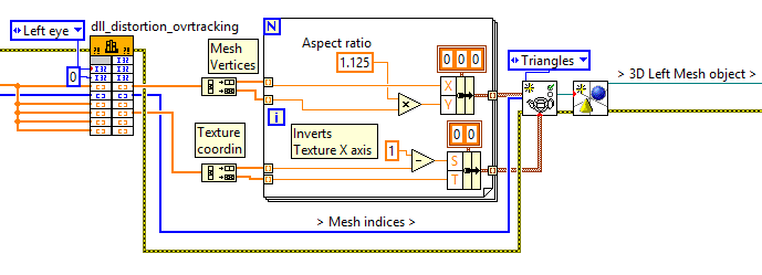
LabVIEW code to generate the left mesh.
Once the mesh is created along with the texture coordinates, images can be applied to the mesh using the Apply Mesh VI from the 3D picture tool set. An example of projection of one image projected on the mesh as texture is shown below.
The image on left projected as texture on one of the meshes (right). The aspect ratio of the mesh is 1.125.
The two distortion meshes are displayed in two 3D picture tool controls that are configured to match the Oculus Rift window in the extend desktop mode. These two 3D picture controls are called 3D View Right and 3D View Left, and will be the outputs seen by the user wearing the Oculus Rift.
This approach of using textures on meshes to correct for distortions means that the 3D object handling must be done for 3D picture controls different from those used for outputs on the Oculus Rift. Two 3D picture controls are therefore put on the front panel of the same VI used for the right and left 3D picture controls showing the meshes but in a hidden area of the front panel. Those two picture controls are called 3D process right and 3D process left. Making these controls invisible or in the back of the 3D View picture controls does not produce consistent results. Another option is to use the "Setup Window" VI to create two hidden windows to render the 3D scenes. However, with the "Setup Window", the "Render Image" step is significantly slower than when using 3D picture controls, to the point of making the real-time operations impractical.
The 3D objects handling and camera positioning is done for the two process 3D picture controls. Images are corrected by obtaining 2D rendered images using “Render to Image” property node. The obtained images are then applied to the mesh using the “Apply texture” VI as shown below.
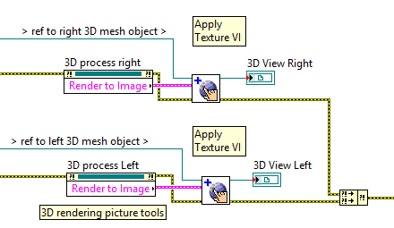
Rendered image applied to texture.
Results
The "Render to Image" step is extremely time consuming. Without distortion correction, the original application could render stereo images at rates exceeding 40 Hz on a I7-CPU laptop with a NVIDIA Quadro K1100M graphic card (the released application was limited at 30 Hz refresh rate to match the Kinect acquisition rate). Adding the distortion correction in the manner explained above makes the refresh rate drop to around 5 Hz. However, the resolution of the rendered images can be changed without affecting the size of the final output. Keeping the same dimensions for the two 3D View picture controls (940x940 each), the dimensions of the 3D process picture controls can be reduced to improve the render rates. Reducing the dimensions of the 3D process picture controls from 940x940 to 600x600 increases the render rates from arround 5 Hz to around 15 Hz, which appears acceptable for the current application. The figure below shows an example of the two 3D View picture controls.
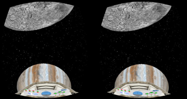
Stereo images corrected for pin cushion distortion.
Summary
The 3D Picture tools provided by LabVIEW can be used to rapidly develop applications where 3D visualization might be necessary. Some of those 3D visualization applications might benefit from the use of the Oculus Rift, as it was demonstrated earlier. The use of the “Render to Image” property of the 3D picture controls provides an output that can be used to produce images on the Oculus Rift that are compensated for lens distortion. However, the “Render to Image” property appears extremely processing intensive, possibly requiring to reduce the resolution of the rendered images to reach acceptable rendering rates. The resulting resolutions and rendering rates might be acceptable for some applications when using a high-end laptop with the Oculus Rift.
Concerning chromatic aberration correction, it would be necessary to separate the output of the “Render to Image” into three separate images corresponding to the red, green, and blue color components. The three images are then used as separate textures to be applied to the same mesh using the texture coordinates provided by the Oculus Rift corresponding to each color components. The vignette factor is simply an intensity factor applied to the texture values near the edges of the mesh. Combining the three textures from the color components and applying the vignette factors require processing on the texture that does not appear to be available with the LabVIEW 3D picture tools. This processing might require to develop code but the goal is to use the ease of development provided by LabVIEW 3D picture tools. If anyone has an idea how to use LabVIEW to do this additional processing, please, let me know.
Let me know if anyone is interested to get executables demonstrating the application shown above right now. I would then post the executables here. The code developed for the Oculus Rift should soon be made available within a new version of the Haro3D library(https://decibel.ni.com/content/docs/DOC-40832) along with the code of similar examples.
