From Friday, April 19th (11:00 PM CDT) through Saturday, April 20th (2:00 PM CDT), 2024, ni.com will undergo system upgrades that may result in temporary service interruption.
We appreciate your patience as we improve our online experience.
From Friday, April 19th (11:00 PM CDT) through Saturday, April 20th (2:00 PM CDT), 2024, ni.com will undergo system upgrades that may result in temporary service interruption.
We appreciate your patience as we improve our online experience.
Contact Information
University: Cardiff University
Team Members (with year of graduation): Nyle Parker (2015)
Project Supervisor: Dr Rhys Pullin
Email Address: creeds1@cardiff.ac.uk
Project Information
Title: Dragon-Log: Utilisation of myRIO for Formula Student Data Acquisition
Description:
The purpose of this project was to develop a way of extracting data from the programmable ECU (MoTeC) embedded in Cardiff Racing’s Formula Student car (CR11) by interfacing with the industry standard CAN Bus protocol which the MoTeC employs. The myRIO device simultaneously provides its own data logging capabilities, which have been utilised in regards to recording strain gauge measurements from in house electronics.
The collected data can help us make informed decisions about future iterations of the Formula Student vehicle design. As well as acquiring real-time data from the ECU, the myRIO was also used for strain measurements - determining various load conditions on components to influence future designs.
Products:
Hardware:
Software:
The Challenge:
The primary aim of the Formula Student project is to design, build and test a car capable of retaining Cardiff Racing’s top 10 ranking at the prestigious Formula Student UK event held at the Silverstone Circuit every year. To achieve this, it is vital that a reliable and lightweight car is produced, ensuring that the maximum performance is extracted from each and every component.
Our myRIO based smart data-logger plays a key part of the overall project - enabling a simple method of extracting strain measurements, while also allowing for active monitoring of the vehicles systems. This ensures that new vehicle designs are based-off of real world data - not just theoretical calculations and simulation models as past cars have used.
In previous years the team and the drivers at Cardiff Racing have very little information about their speed or the current gear. Previously drivers had to listen to the engine to know when to change gear, and then count up/down in their head to know which gear they were in. This is obviously not ideal when concentrating on racing.
The main aims for our myRIO based smart data-logger were to:
The Solution:
Smart Data Logger System Overview:
A National Instruments myRIO 1900 was selected for use as the controller for this application. With a mass of only 193g and dimensions of 88.6 x 24.7 x 136.6 mm, the myRIO is a truly compact controller. It also has a sufficient number of analogue/digital inputs/outputs our requirements.
A macro overview of the electronic system is given in Figure 1. Within the dotted lines is the main system. The arrows show the basic flow of information, allowing the fundamental concept of receiving and storing data from the MoTeC ECU. The data from the MoTeC ECU uses its own protocol with a strict set of rules that govern how it functions. Communication is achieved by the flow of CAN frames between the MoTeC and the myRIO via the Stratom X-CAN adapter which facilitates this communication.
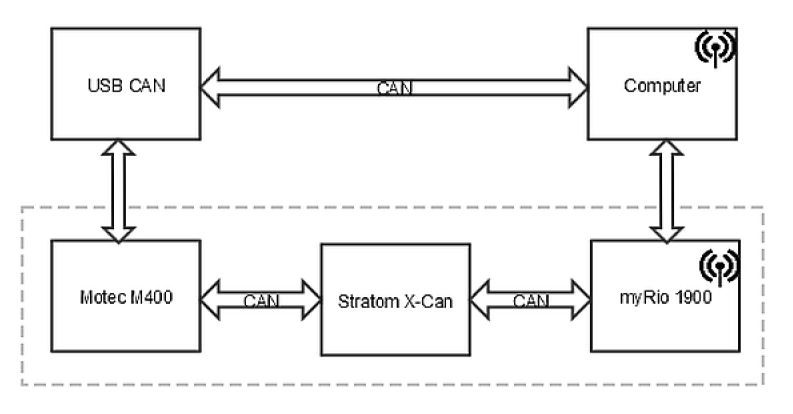 Figure 1 - System Macro overview
The X-CAN adapter was connected to the MoTeC 400 via the standard three wires. Can HI, Can LO and Ground. In this project the X-CAN adapter was connected with a Molex connection, where the three wires are clamped in terminal blocks.
MoTeC CAN Configuration:
The MoTeC M400 can be configured to send customised data-sets where the required sensors are chosen, and their place within the CAN frames configured. By connecting the ECU to a laptop via the CAN-USB adapter, the user can navigate to the CAN setup menu as shown in Figure 2 and ensure that the MoTeC M400 is configured to send a customised data set on CAN 0, where the numeric value 8 defines “Custom data set 1, sequential”. This project made use of sequential transmission as it is easier to sort through the data when it is received due to its structure.
 Figure 2 - MoTeC CAN setup menu
By using sequential transmission the channels are sent on sequential addresses until all the data has been sent. There is no need to use two bytes for the header, so each CAN frame is then capable of sending four Channels of data (two bytes per channel). For every four channels sequentially sent, the address changes by incrementing the value of the identifier.
With the MoTeC setup up to send 16 channels of data using the CAN protocol. As soon as the MoTeC is switched on, during normal operation, it will be sending four CAN frames with the data ordered as seen in Table 1.
Table 1 - CAN frame structure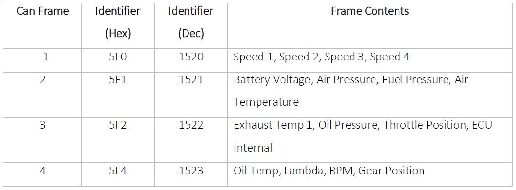
X-CAN LabVIEW Interface:
Once the MoTeC has been configured to transmit the channels in the desired manner, an interface was required to connect the ECU to the myRIO device. The X-CAN is a CAN 2.0 interface, designed for myRIO MXP connectors.
We adapted the LabVIEW VI’s provided by Stratom for our data logger. Firstly an X-CAN session is established between the MoTeC and the myRIO. The options here are straightforward, a bus speed is selected, in this case 500kbps, and the desired MXP adapter slot B chosen. The X-CAN session out is then transmitted to the main while loop. As can be seen in the code snippet shown in Figure 3 the X-CAN session will be stored to a cluster, which takes the form of a CAN frame. Each frame contains eight bytes of data, two bytes per channel (sensor). This is used as a high level function for the reading and writing of CAN data for the CAN device. The CAN frame is then passed to a custom sub VI for processing and sorting.
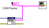
Figure 3 – X-CAN session establishment
The unbundled can frame is passed to a case statement, which makes use of the decimal representation of the identifier. There are five cases defined, with the default being used to ensure all LEDs on the myRIO are switched off. This has been done as in the other cases they have been programmed to turn on when in receipt of a specific frame. The remaining cases are for the four frames of data (1520, 1521, 1522, 1523). LED0 will be illuminated in receipt of CAN frame 1, LED1 for frame 2, LED2 for frame 3, LED3 for frame 4.
The payload is passed to an indexed array, such that the relevant bytes of data can be extracted. In this case, CAN frame 1 has been sent, with its payload being indexed to output bytes 0, 1 which will be passed to a calculation state which will output the wheel speed as shown in Figure 4.
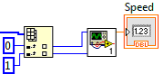
Figure 4 - Sorting bytes
The two bytes of data taken as being CAN HI and CAN LO are combined, with the output scaled based upon a factor which has been provided by the company MoTeC in their user manual. The final result is a DBL representing the speed, shown in Figure 5.
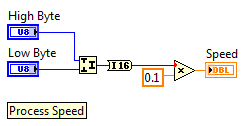
Figure 5 - Converting to real value
The same process is applied to the other channels. Each processed using this same method; the only difference will involve the scaling factor used, - fortunately this is provided for each channel type by MoTeC.
Figure 6 shows the user interface, which has been designed to allow the user to view the data clearly and simply. Wheel speeds are displayed using gauges, temperatures with thermometers and CAN frames with data displays. The ability to view live data has proved highly beneficial, enabling any immediate problems (such as overheating) to be identified early. The greatest benefit will come from post analysis of the stored data, as a thorough investigation can take place to characterise overall performance.
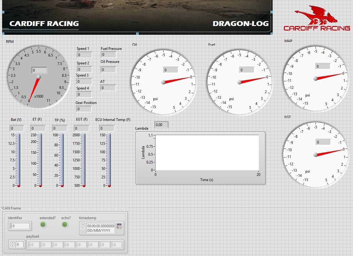
Figure 6 - LabVIEW front panel
A producer and consumer architecture was adopted – which was important to ensuring data integrity. The queues used to transmit data between sections of our code provide a buffer - preventing data losses when the data cannot be read/stored fast enough.
Strain Gauge Amplifier:
Testing undertaken on CR10, the previous year’s Cardiff Racing car, used an NI CompactDAQ device to extract data from the car, hardwired directly to a tablet computer. Each strain reading was then passed through a Vishay signal amplifier. Housed in a separate sidepod, the cDAQ system contributed approximately 10kg to the total mass of the car (see Figure 7). This makes such a setup only viable for non-competitive testing – which is not ideal as we couldn’t gather data at the competition where the data is most beneficial.
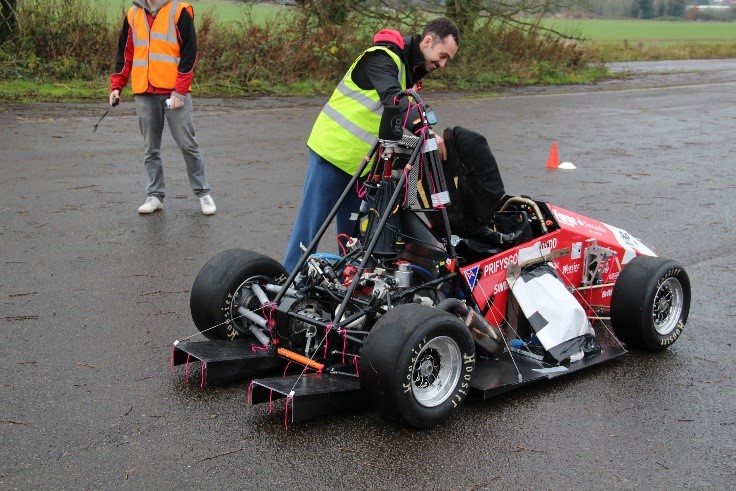
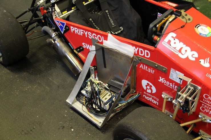
Figure 7 - CR10 With additional electronics logging side pod
In light of this, we wanted to developed a lightweight system to easily integrate into the new design of this year’s car, CR11. The myRIO was ideal for this. However, because we could no longer access the quick and easy signal conditioning provided by the cDAQ’s C-series modules, we built and tested our own full-bridge strain gauge amplifier. Testing of the final design is shown in Figure 8.
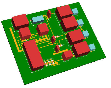
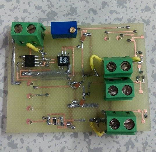
Figure 8 – 3D PCB design and assembled PCB
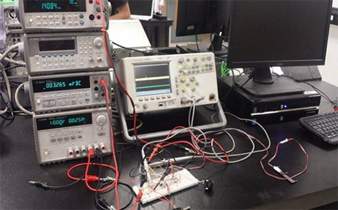
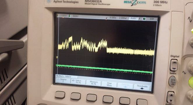
Figure 9 - Breadboard testing of the final circuit design
The final solution is based around the AD620AN instrumentation amplifier. The amplifier outputs an analogue signal between 0-5V. This is then connected to one of the analogue channels on the myRIO, where it is sampled and processed to calculate the strain.
The physical size of the amplifier allows for it to be located in close proximity to the bridge to reduce the signal noise allowing for better data collection. The wiring for the amplifier could then be integrating in to the cars main wiring loom, leaving the bridge as it is. This will improve the tidiness and simplify the routing of the wiring around the car where the loom is protected by heat shrink.
Housing:
The myRIO and all associated electronics needed to be integrated into Cardiff Racing’s new car; CR11. As such, they will be exposed to a number of harsh including varying weather, vibration from the engine and lateral loading (G-force). Therefore a suitable location had to be chosen, that would still allow easily access for maintenance and connecting external devices.
It was decided that all the electronics associated with the Formula Student car were to be housed in an insulated, protective casing in the cars side pod within a dedicated electronics section. This aided the protection of the delicate components from being knocked by the driver or impacted by stones thrown up whilst the car is being driven.

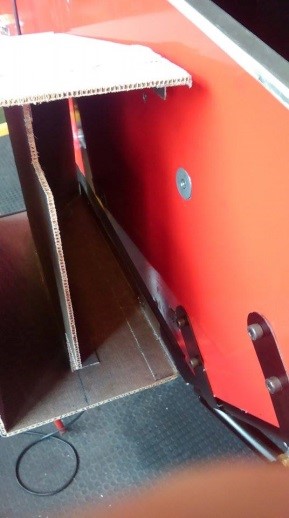
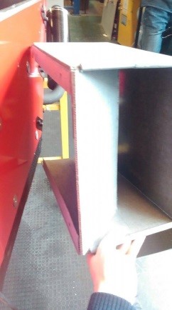
Figure 10 - Electronics box and side pod
Future Expansion:
Two myRIO’s were used for this project with the intention of one being permanently fixed to the Formula Student car, and the other as a desktop station for programming and debugging of new code. The desktop myRIO was also used to train additional members of the Formula Student team in LabVIEW for future development. The flexibility of the NI platform allows a lot of scope for future expansion. For instance, we could also use the myRIO to acquire/analyse/display engines temperature and G-force. In addition, the team would like to go wireless in the future – allowing us to changing of settings from the pit wall. The myRIOs integrated WiFi capabilities will simplify this enormously.
Conclusion:
This project was facilitated with aid of National Instruments, offering assistance to the Cardiff University Formula Student team in this 2014/15 season. The myRIO’s and X-CAN adapter enabled us to capture valuable information that was previously impossible. LabVIEW is an excellent tool for Formula Student teams – it is very powerful and flexible, but best of all it can be learned very quickly and easily. Additionally, the intuitive nature of LabVIEW allows for the flow of data to be visualised – which benefits the inevitable debugging of our custom software, in contrast to scripted code which is far more difficult to debug and fix.
National Instruments also offered invaluable support with any technical challenges we encountered. A comparison to ‘LEGO’ may be the closest thing for someone who has never used LabVIEW before; using “building blocks” to create powerful software is both intuitive and very addictive!
The NI platform enabled rapid system development – the entire project was completed in just 6 months by a single undergraduate engineer.
This project is part of a larger Formula Student project within Cardiff University that had many more members involved. Although our myRIO-powered smart data logger is now complete – there is still a lot of work to do to get out CR11 Formula Student car race-ready for Silverstone on July 9th.
Please keep an eye out for future developments of this project via Cardiff Racing’s website: www.cardiffracing.co.uk.
Attach Poster
Poster, report and LabVIEW code can be found attached.
More information can also be found at: www.cardiffracing.co.uk/cr11.html
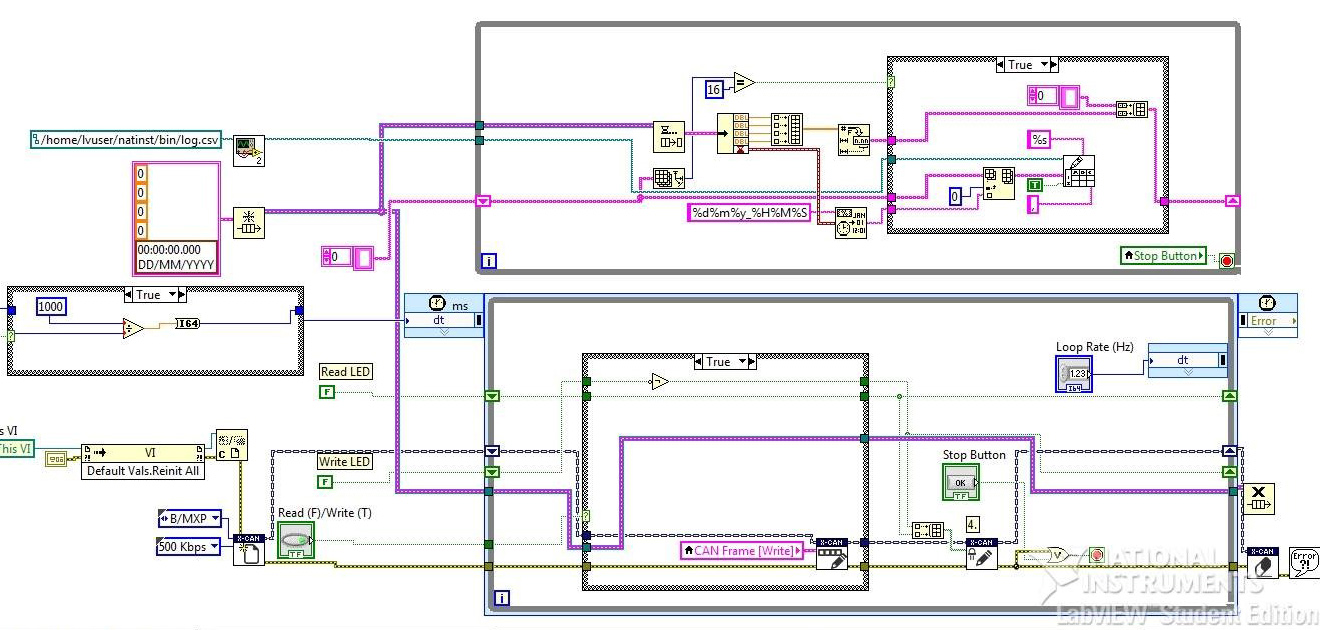
Figure 11 - RT Main VI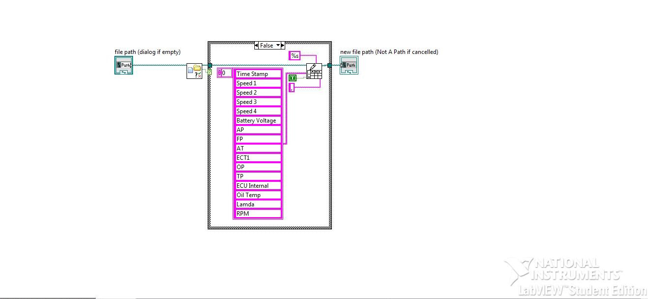
Figure 12 - File Check VI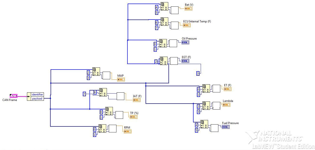
Figure 13 - Just Frame VI
Nominate Your Professor
I would like to nominate Dr. Rhys Pullin as not only has he overseen the Formula Student Project in its entirety and managed it very well this year, but he has given great motivation to all students involved with the larger project as a whole. This project was just one in a long line of things to make the overall car complete for the Formula Student competition. Without the help and direction of Dr Pullin in scheduling the work undertaken by all the students, this project would not have been possible.
Aquiring data will always make a better car and a better engineer. Fantastic report and concept, I hope to see this integrated in the future at Cardiff Racing!
Having data to analyse will greatly help Cardiff Racing in developing areas of the car.
