From Friday, April 19th (11:00 PM CDT) through Saturday, April 20th (2:00 PM CDT), 2024, ni.com will undergo system upgrades that may result in temporary service interruption.
We appreciate your patience as we improve our online experience.
From Friday, April 19th (11:00 PM CDT) through Saturday, April 20th (2:00 PM CDT), 2024, ni.com will undergo system upgrades that may result in temporary service interruption.
We appreciate your patience as we improve our online experience.
Functional Description
This set of vi's causes a Princeton Applied Research Digital Potentiostat such as a PAR 263A, PAR 273 or PAR Versastat II to record a cyclic voltammogram using the GPIB interface to control the potentiostat's functions. "Cyclic Voltammetry.vi" is the main program vi. It is the user interface by which the scan parameters are set, and it calls various sub-vi's to communicate with the instrument as appropriate.
An update has been uploaded (07/01/09).
The update addresses the timing issues described below. The systems hangs much less often, and the "dead time" between the scan and the transfer of data to the computer has been eliminated. The older version has been removed to avoid confusion.
(1) The "Run CV.vi" now checks status bit 5 ("scan done") rather than bit 2 ("curve done") in a while loop during the scan. This has the effect of making the program pause while data is recorded.
(2) The Query.vi is used to check the potentiostat's status before the first data extraction and after the second data extraction. This has the effect of clearing any error settings and resetting the talk/listen status to prevent hanging.
(3) The updated program executes much more quickly, and is much more satisfying to use than the previous version.
(4) The updates are in Labview 8.0 but should work with minor changes in later versions. (E.g. the name of "save spreadsheet file.vi" is different from 8.0 to 8.2)
Caveats and Additional Notes
This vi does not support "live" display of the CV as it is being recorded, but the CV is displayed and saved after it is recorded. Be patient, but if the talk light is on for more than 20 seconds, the program has crashed... cycle the power on the potentiostat and try again.
The voltammograms recorded will consist of 1020 potential-current pairs. This number is adequate for most scans, but the interval between points may be a little large if large scan ranges are chosen.
For slow scan rates (0.05 sec between points, often slower than 100 mV/s), the potentiostat will record 8 current readings for each potential and will report the average. This feature cuts down on noise at slow scan rates.
There are still some problems with timing on various systems... even though the timing should be controlled through the various "command done," "data ready," and "curve done" status bits returned from a GPIB serial poll. If the system hangs, at this point the easiest thing to do is to stop the program, cycle the power on the potentiostat and try again. The Talk light sometimes stays on after all the data has been downloaded... this problem is still under investigation. If the talk light is on and the system is unresponsive, then stop the program and cycle the power on the potentiostat.
If the I-overload light on the potentiostat lights up, check if the working electrode wires are touching some other metal. If the light still goes on, then the current range is set too sensitive, and should be stepped back. The numbers pon the current range setting are the logarithm of the number of amps per volt. A setting of "-6" corresponds to 1 microamp per volt. A setting of "-5" is ten times less sensitive and corresponds to 10 microamps per volt.
If the E-overload light goes on, then check if the auxilliary and reference electrodes are in solution and functional. Make sure that no wires are touching each other or other metal. The Ametek-Princeton Applied Research website has great technical bulletins about reference electrodes, resistence etc available. If the E-overload light goes on, you will be lucky to get any data at all, but if you do, you should be suspicious of it and try another scan.
The filter referred to is the 5.8 kHz (or so) low pass internal filter in the potentiostat. It distorts data at high scan rates... use it only below 400 mV/s.
"Cyclic Voltammetry.vi" is the main program. The user sets the initial potential, two switching potentials, the final potential, the scan rate, equilibration time, sensitivity, and filter status. The program checks for obvious errors, such as a scan range or scan rate greater than what the potentiostat can handle and then calls a series of vi's to control the potentiostat.
"Initialize Pstat for CV.vi" clears the GPIB interface and restores default parameters to the potentiostat in preparation for receiving CV parameters.
"Set up CV.vi" takes the user parameters, translates them into the potentiostat's command set, and sends them via the GPIB interface. For example, it sets the Bias potential to the middle of the scan range, and then the potentiostat can scan within 2 V positive or 2V negative of the Bias value. It causes the potentiostat to assemble the waveform it will apply. A total of 1020 readings of current will be recorded.
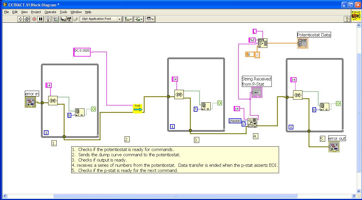
"Extract.vi" downloads the waveform from the potentiostat to serve as the X-axis values (potential) of the CV. The potentials are translated into mV applied by the main program. Here is a screenshot of the block diagram:
"Run CV.vi" sends the command to turn on the cell, wait the specified delay time, record the CV data, and wait until the CV has finished recording before sending other commands.
The second instance of "Extract.vi" downloads the current readings. The current readings are translated into Amps by the main program.
The potential, current pairs are displayed on the graph on the front panel and are saved as a text spreadsheet file. the user is prompted for a filename. The scan parameters are saved as the same filename but with the ".hdr" extension added.
A second instance of "Set up CV.vi" is called to clear the GPIB and potentiostat of any errors incurred while the program is running.
Two other vi's are included. "Send.vi" sends commands to the potentiostat which do not elicit a response. "Query.vi" sends commands to the potentiostat which do elicit responses. They both rely on the "command done" status bit to control the flow of their execution.
This program is based on the Quickbasic programs (described and available in my blog), that I developed in the 1990's when I was working in Vermont with the Geiger group. It is not as snazzy as commercial software, but it will record CV's.
Previous and current (CHE 0911537) support by NSF is gratefully acknowledged for this work.
Example code from the Example Code Exchange in the NI Community is licensed with the MIT license.
Can I use this VI to measure CV on PAR 283?
I don't have much experience with the 283, but if it uses the same command set as the other potentiostats (likely) then there should be no problem, other than minor adjustments.
These programs assume that the potentiostat is at GPIB address 14 (factory default) ... other addresses will require a little editing.
Dear Mike, I think your VIs are made in 8.5 version. I can not open in my 8.2 version. Is there any possibility if you save your VIs in lower version as 8.2 and upload again.
I will appreciate your support
These vi's are from the 8.0 full development system since that is what is on the computers which are attached to my potentiostat. Maybe you do not have the full development system?
When I try to execute Cyclic Voltammetry.vi, it "runs" in ~15s and prompts me for a filename. If I do some searching, labview blames the instance of Query.vi inside Initialize the Pstat for CV.vi. The annoying thing is, if I run Query.vi independently, it works just fine (e.g. Querying "ST" to the 273a returns "16". Any help would be appreciated. Thanks!
hey!
I'm running from one meeting to another so I don't have much time right
now.Can you check to see if the potentiostat is set to GPIB address 14? If
so, can you use NI's Measurement and Automation Explorer to check if the
GPIB communication is all right? Try sending "CELL 1" to the potentiostat.
that should turn the cell on. "CELL 0" should turn the cell off.
Let me know what you get.
Mike
Yes, the address is set correctly. The automation explorer does not see any gpib problems. Sending "CELL 1" and "CELL 0" turns the cell on and off. The QUERY.vi and SEND.vi seem to work fine if I use them manually to send commands. Upon running "Initialize Pstat for CV.vi" the 273a immediately turns on its error light and the program takes ~30s to complete. If I delete the clear gpib command in "Initialize Pstat for CV.vi", this vi does not report any errors and completes within 2s. The 273a, however, immediately turns on its error light on the front panel.
Some more miscellaneous things to check:
Do you have the potentiostat set to "CR" or "CR-LF" as the terminator character? It should be "CR". You might want to check that the terminator character in MAX (GPIB properties) is set to 13, which is the same as "CR".
Error 16 on the potentiostat reports an overload condition, such as the brief current overload that may occur when the cell is switched on. The OVER command can be sent with QUERY.vi to clear this condition. An overload error should not affect the running of the program.
The 273 can only accept commands at a fairly slow rate. I would set the GPIB properties in MAX to the slowest possible bus rate (2 microseconds or more).
Sometimes a loose GPIB cable can lead to problems when multiple commands are sent quickly... disconnect the cable, clean the pins with a tissue and reconnect the cable firmly.
Make sure you are using the CV_PAR_PSTATupdate1_LV8.0.zip files (http://decibel.ni.com/content/docs/DOC-4365) since the older files are more error-prone, even on the PAR 263A and Versastat that I use to test them out. They should work fine on the 273, but there's the possibility that there's something very subtle I have missed between the two types of instrument. If you are using a different version of the files, make sure you get rid of the older versions completely since Labview sometimes uses a vi it has previously accessed rather than a new one.
Do you have a cell set up to test the program out? If not, you can use something like a one-megaohm resistor with the working electrode lead (green) attached to one side and the reference and auxilliary (white and red, respectively) leads attached to the other end. With this resistor, you would need a current range setting of "-6" which is really 1E-6 Amps per volt. A CV run from 0 to 1000 to -1000 to 0 (all mV) at maybe 200 mV/s should just show a diagonal line corresponding to Ohm's Law.
What does the file that the program generates look like? It should be 2 columns, the first being potential and the second being current. If the second column is all zeroes, you may want to add a few seconds time delay in the "EXTRACT.vi" right before the data is read from the GPIB.
I hope these help,
Mike Shaw
Another thought.... the QUERY.vi checks whether the "command done" bit it set before a new command is set. At least that's the theory. The reality is that the status bit is set just before the potentiostat is actually ready. Computers are so fast now that this mismatch has become a problem.
I made a modified version of QUERY.vi for the bulk electrolysis program which is in LV_8_0_Bulk_electrolysis_2010_08.zip on the http://decibel.ni.com/content/docs/DOC-4097 page. The modified version is called QUERY2.vi, bu if you rename it and use it in the CV program, then some of the errors might be addressed. I have basically added a delay between when the status bit it read and when the command is sent.
What you've told me about the problem sounds like a communication issue. You might also try adding small delays here and there so that commands from the PC don't come at the potentiostat too fast.
I hope this helps,
Mike Shaw
Mike,
The first instance of "Extract" has been causing me some problems. Every time the "GPIB Read" sub VI runs, the red error light on the PAR 273A turns on right after it spits out the X-data. The X-data ranges from -8000 to 8000 (although I don't have any of the inputs on the "Set up CV" VI to anything greater than 2000 mV). Additionally, after "8000", the following string appears: "-1,-1,-1,-1,-1,-1,-1,-1,4096,0,0,0,-30720,0,0,0,-1,-1,-1,-1,"
I'm confused as to what is going on and why I'm having these problems. Do you have any ideas as to what is happening?
Thanks,
Todd
HI!
I’m not sure that my previous messages got through. Sorry if this a is a repost.
The setting of 8000 corresponds to 2000 mV… The programmable DAC has 0.25 mV resolution, so any setting you enter gets multiplied by 4. There is also the BIAS DAC, which has 1 mV resolution… The program will choose a BIAS setting so that you can scan a total 4-Volt range. The upshot is that the settings of 8000 are OK and expected when you enter 2000 mV.
The readings of random numbers at the end of your first transfer are troubling. Most problems with the PAR 276/273 etc are because of the timing of communication. The “Extract” VI just waits for when the data is ready… but the PAR273 prematurely reports its readiness with a fast computer (i.e. anything modern).
I can suggest 2 possibilities:
(1) Easy: add delay of 2 seconds between the “while loop” and the GPIB read command.
(2) Only slightly less easy: Have the while loop check the “command done” and “curve done” status bytes (byte 0 and 5) in addition to “output ready” (byte 7). Maybe add a “SENDIFC” command if an error is encountered.
(3) Hopefully you don’t need to do both.
I ran into this type of problem with the electrolysis program (posted) and I came up with the procedures in “Query2.vi.” In the first incarnation of the Query vi., I checked “command done” before and after I sent a command which required a response. Adding the “output ready” check, and the “SENDIFC” if an error is encountered has increased the stability of the electrolysis program. At the current time, I have not observed the electrolysis program hanging.
I hope this helps,
Mike
why don't use SETE instruction instead of BIAS and set the voltage directly ??
The potentiostat has a “BIAS DAC” and a “Modulation DAC” each with a range from -2V to +2V. The modulation DAC is what a waveform (such as a CV) would use. If you only use the modulation DAC, you are limited to a -2V to +2 V window. The BIAS DAC allows you to offset the center of that window.
I believe SETE uses the modulation DAC. If so, then using SETE alone would not allow for a potential outside the -2V to +2V window to be applied. Note that the potentiostat can only scan over a total of a 4V range, no matter what the starting point is.
Basically, I used the approach recommended in the documentation.
Mike, I have the same problem as what pacauate have.
I tried to run vi's indivually but I had a problem in Initialize Pstat for CV.vi and Extract.vi
The problems are exactly the same.
Is there any solution to solve it? how can I check "terminator character in MAX (GPIB properties) is set to 13, which is the same as "CR"."?
I cannot find this
I am using 273A with GPIB-USB-HS from National Instrument
Hi!
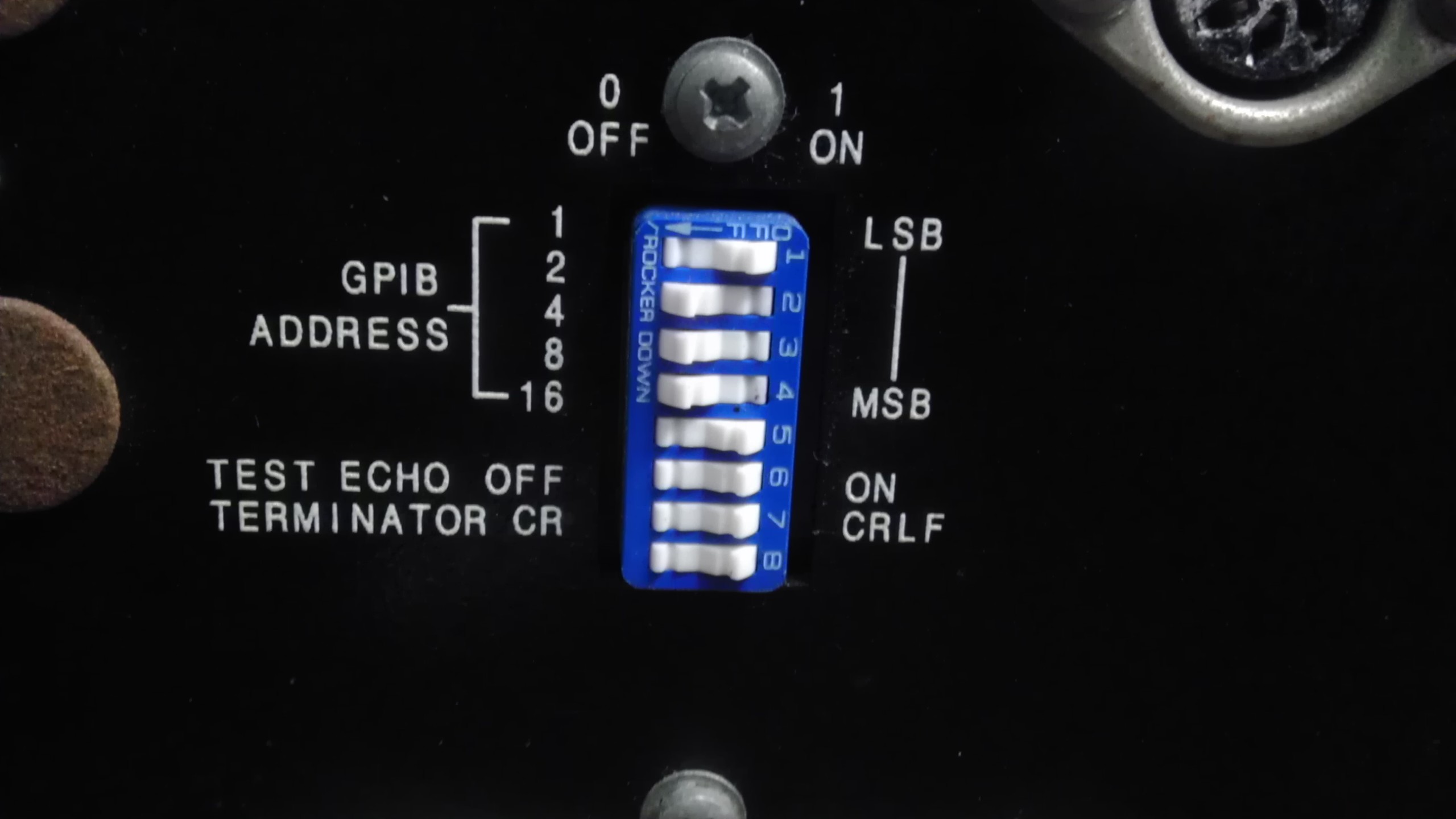
Here's a photo of the dip switch settings on my PAR 263A, which is the same as the PAR 273A. The first 5 switches define the GPIB address. Mine is set to "14". The next switch turns off the "echo" setting, which is necessary. The switch after that sets the terminator character to CR (carriage return). The bottom switch apparently does not do anything.
You might want to use the NI software to send "CELL 1" and "CELL 0" commands to see if the communication via gpib is working before you try the labview software.
I hope this helps!
Yes, sending CELL works properly and I am using CR instead of CRLF.
but as orangefrog said I have following problem
1) Upon running "Initialize Pstat for CV.vi" the 273a immediately turns on its error light and the program takes ~30s to complete.
2) "Extract" problem, it is not working... listen light turned on and did not spit out any data
Do you have any Idea about this?
Thank you so much
Benjamin
I haven't had time recently to update the CV program, but you might want to try what I recommended to orangefrog, which I have copied here:
--------------------------------------
Another thought.... the QUERY.vi checks whether the "command done" bit it set before a new command is set. At least that's the theory. The reality is that the status bit is set just before the potentiostat is actually ready. Computers are so fast now that this mismatch has become a problem.
I made a modified version of QUERY.vi for the bulk electrolysis program which is in LV_8_0_Bulk_electrolysis_2010_08.zip on the http://decibel.ni.com/content/docs/DOC-4097 page. The modified version is called QUERY2.vi, but if you rename it and use it in the CV program, then some of the errors might be addressed. I have basically added a delay between when the status bit it read and when the command is sent.
What you've told me about the problem sounds like a communication issue. You might also try adding small delays here and there so that commands from the PC don't come at the potentiostat too fast.
Hi, I have a problem, when I change the driver to set "TP" (take point) I read online the potetiostat without any problem, but when i try to increace the rate, with "TMB" to a No Frills mode, and have a faster reading, always my driver hang up. what can I do?? please.
Sorry for the delay... my life has become busier.
Here is my opinion. Point-by-point measurements are going to be limited by the speed of the potentiostat's interface. If commands are sent to the potentiostat before the potentiostat is ready, the system will hang.
You must make sure that you check the status bit between commands and only send the command when the status bit indicates that the potentiostat is ready. You can check the staus byte via GPIB or use the ST command... they are equivalent
The ST command returns a decimal number that is broken up according to:
"Command done?" is bit 0 (decimal value = 1)
"Command error?" is bit 1 (decimal value = 2)
"Curve done?" is bit 2 (decimal value = 4)
Bit 3 is not used (decimal value = 😎
"Overload?" is bit 4 (decimal value = 16)
"Sweep done?" is bit 5 (decimal value = 32)
"Service requested?" is bit 6 (decimal value = 64)
"Output ready?" is bit 7 (decimal value = 128)
Values of "false" set the bits to zero, true sets them to 1.
You want to wait until bit 0 and bit 7 are both set to values of true. If bit 1 is set to true, then sending (and receiving the output from) an ST command will reset.
I would not let an error condition persist for too long. I have had the experience where i have o reboot if an error state was left for a minute (or so... its a little arbitrary), but can recover if an ST command is sent )and feedback received) properly.
Essentially, the update to the Query.vi mentioned in messages above contains the implementation of these ideas. I also make sure that the "curve done" bit is checked, too.
I have an impression that computeres today are so fast that commands can get sent while the status bit is changing, so a little extra delay does not hurt. All of this limits the maximum rate at which you can collect data, unfortunately.
A better solution is to use the potentiostat as an analogue device, and use a DAQ device to control the potential and record the applied potential and current, as discussed in the "Cyclic voltammetry using an analogue potentiostat" documented posted elsewhere. I use a NI-USB-6251-BNC and can collect CV's at 200 V/s using a microelectrode with this softaware.
