From Friday, April 19th (11:00 PM CDT) through Saturday, April 20th (2:00 PM CDT), 2024, ni.com will undergo system upgrades that may result in temporary service interruption.
We appreciate your patience as we improve our online experience.
From Friday, April 19th (11:00 PM CDT) through Saturday, April 20th (2:00 PM CDT), 2024, ni.com will undergo system upgrades that may result in temporary service interruption.
We appreciate your patience as we improve our online experience.
Contact Information
Competition Year: 2017
University: Cardiff University
Faculty Advisers: Ryan Marks
Email Address: willisjc@cardiff.ac.uk
Country: UK
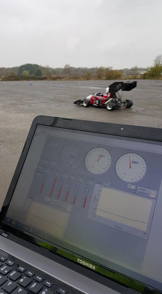
Figure 1 -Early testing of the syestem
Project Information
Title: F1 inspired Wireless Telemetry and Data Logging System for a Formula Student Car
Description:
For this project an inexpensive wireless telemetry system for a formula student car has be developed. The purpose of the project is to give remote monitoring of the Formula Studnet car's engine and other systems. The benefit of seeing this data live is to help protect the cars system of failure, for example stopping the engine before overheating. The second feature of the system is logging to file. While viewing the data wireless is very useful, post processing of the data is also possible.
The project video with Overdrive UK, a motorsports Youtube channel:
Figure 2 -Interview with Overdrive UK
To develop a wireless monitoring system for Cardiff racing Forumla Student car. It needs to display all the car's engine and other systems remotly. The key advantage of have wireless telemetry is being able to get the data to analysis engineers in real time. The benefits of which fall into two main categories; heath management of the car and driver development.
Formula Student is a student engineering competition held annually in the UK as well as other European venues. Student teams from different universities around the world design, build, test, and race a small-scale formula style racing cars. The cars are judged on a number of criteria split into static events and dynamic events.
Static events include engineering design, cost, manufacturing and sustainability and business presentation judging. Dynamic events include acceleration, skid-pad (figure of 8), autocross, efficiency and a 22km endurance.
The competition is organised by the Institution of Mechanical Engineers (IMechE) and uses the same rules as the original Formula SAE based in the USA.
Cardiff Racing is a formula student team made up from engineering students at Cardiff University, every year they design and build a single seater race car to enter into the IMechE Formula Student competition in the UK as well as other European competitions. The main design team is formed by fourth year students studying automotive design module, as well as 3rd year students who have chosen projects related to the car. They are also from volunteers from all years looking to develop practical engineering skills.
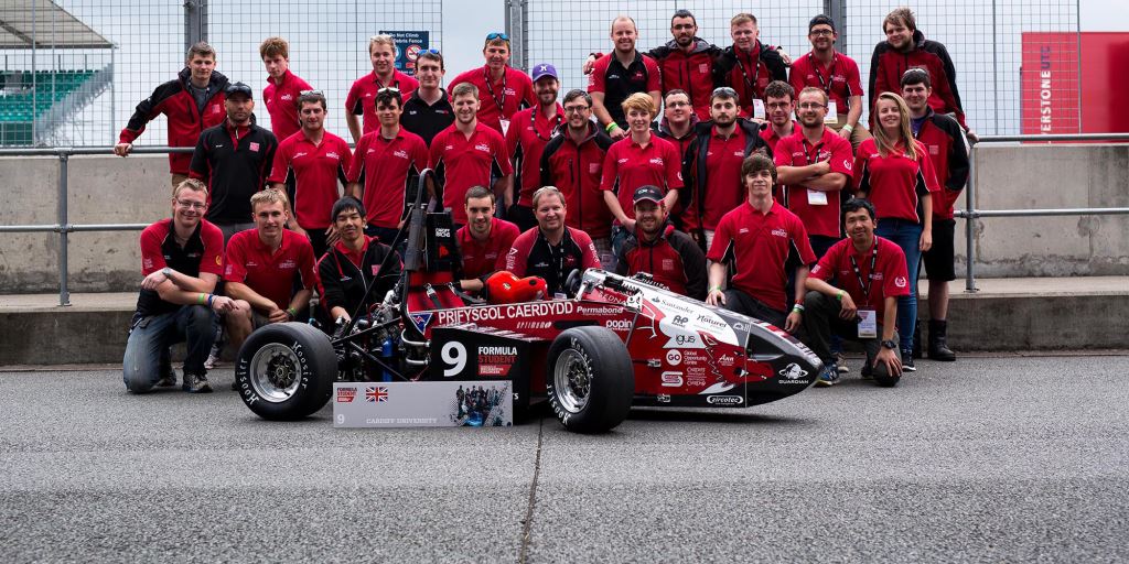
Figure 3 -Team at Silverstone 2015
This year’s car, CR12, will be a continued evolution of last year’s car CR11. This year will look at further developing an aero package, while keeping the overall weight down, ideally under 190kg. The body will continue with a front Aluminium monocoque with rear spaceframe where the engine will mount. The formula student rules restrict engine size to 610cc. This limits engine choice to in general motorbike engines. CR12 will use an 553cc Aprilia SXV 550 V-twin. The engine will be controlled by a MoTeC M400 engine control unit (ECU).
For this project an inexpensive wireless telemetry system for a formula student car has be developed. The purpose of the project is to give remote monitoring of the car’s engine and other systems. The benefit of seeing this data live is to help protect the cars system of failure, for example stopping the engine before overheating. The second feature of the system is logging to file. While viewing the data wireless is very useful, post processing of the data is also possible.
The system will be LabVIEW based with more of a focus on weight and packaging for the formula student car.
The system was required to interact with many other sub systems on the car. Most of this was done using the controller area network (CAN) bus. The currently used ECU is a MoTeC M400. This is used for engine control, fuel tables, etc. All of the data from the MoTeC can be sent over the CAN bus such as engine temps and O2 readings. Another key system to record data from is the power distribution module (PDM). The model used is the MoTeC PDM 15. This once again uses the CAN bus to transfer data and can send important information such as voltages and currents of the 15 power rails on the PDM.
The MoTeC M400 ECU can be quite limited in term of number of inputs and outputs, the myRIO implementing the system on will have some DAQ functionality to allow for additional sensors if needed.
The myRIO itself is not able to receive CAN messages as it does not have the required transceiver. A partner of National Instruments, Stratom manufactures an add on module called the X-CAN. This small unit attaches to one of the myRIO Expansion Ports (MXPs) ports. It has on board the needed microchips to send and receive CAN messages at 1Mbit/s (the rate of the MoTeC and PDM). Along with this, the X-CAN has an application program interface (API) for LabVIEW for ease of integration.The myRIO was chosen as the platform to develop the system on. It uses an embedded duel-core ARM processor alongside an FPGA which is used for control of the sampling of the many inputs and outputs. Because of this the myRIO can run independently of a computer as it is able to run a built-in Linux based operating system. This is ideal as it can be installed in to the car with no space required for a host computer.
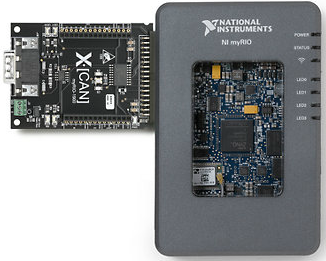
Figure 4 - myRIO with X-CAN
The software for the system has been fully integrated in LabVIEW and will have two parts; the myRIO running in the car itself, while a laptop (or any other windows base PC) will run a user interface to present the received telemetry, this is shown in Figure 5.
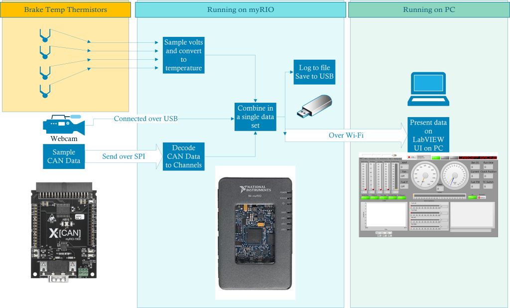 Figure 5 - Software overview
The myRIO runs 4 while loops repeating the code indefinitely from boot up to shut down, each responsible for a different task:
Loop 1: Sampling CAN frames and writing to the PDM
Loop 2: Converting CAN frames to channel data and sampling thermistors data.
Loop 3: Sampling images from camera and writing to a video file
Loop 4: Write data to file
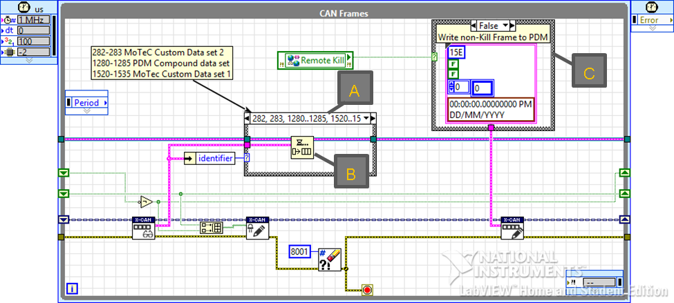 Figure 6 - Loop 1: CAN Sampling
This was then modified to only add frames that are relevant to the system to the queue based on a frames identifier. Thus can be seen in Figure 6 through the use of a case structure (A). Non-relevant frames will not be added to the queue and cleared. This queue gets passed to the next loop for processing (B) as including processing in this loop would lower the sampling rate.
Also in Figure 6 is the way CAN messages are written to the bus to be picked up on the PDM (C). This sends ether 0 or 100 in the first byte with the identifier of 15E (hexadecimal). The PDM is setup to listen to identifier 15E. If the value is not zero, the power rails are turned off killing the car.
This loop dequeues the raw CAN data that was sampled in the first loop and converts it from the 8 bytes into useful channel data for the various monitored channels from the MoTeC and the PDM.
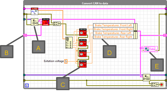 Figure 7 - Loop 2: Convert can to data
From a top level view of the loop seen in Figure 7 the process works by:
A. Raw CAN data is received and converted to channel data
B. Using shift registers (a way of storing data from one iteration to the next), the previous loop iteration dataset cluster is merged with the new channel data received
C. Voltage readings are taken from the thermistors and converted to temperature readings
D. The temperature readings are merged in to the cluster
E. Finally, the new updated dataset cluster is sent to the network shared variable and into another queue to be used by the data logging loop

This subVI, is the main focus of the system and is where the main processing of CAN data happens. Both MoTeC and PDM CAN frames are received here and need to be handled in different ways.

This subVI takes the sampled voltage from a thermistor and converts it into a temperate in Celsius. A thermistor is a device whose resistance changes with temperature. This can be exploited in a voltage divider circuit to give a voltage output that’s proportional to the temperature.
This loop is responsible for grabbing frames from a connected webcam, recording them to file and sending them to the viewing laptop. Instead of using network shared variables like the other communications to the laptop, a free reference library called simple TCP messaging is used (STM). This method of network data transmission is far better for constant streaming like in this case where video is being streamed back. For logging an AVI file is created on the USB stick attached to the myRIO.
The benefit of recording video with data is that any spikes in a data channel can be correlated with the video footage. For example, seeing a high lateral acceleration while the video shows the car going around a corner. This can be used to explain any anomalous data quickly thus help with data analysis.
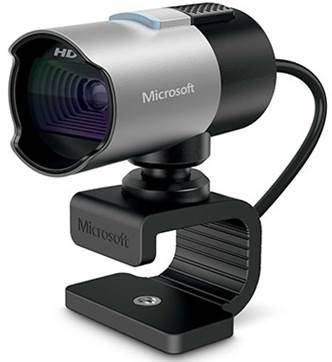
Figure 8 - Webcam used
A relatively inexpensive webcam was used for the system, like the one in Figure 8. This costs of this is under £50 and gives video at a resolution 1080p at 30 frames per second, however this could be easy replaced with a higher performance camera with a high resolution or frame rate (high speed camera).
This is the last loop on the myRIO and is where the final data set cluster from loop 2 is dequeued. Using information on the car name (e.g. CR12) and event (e.g. Silverstone) are sent from the laptop over the network shared variables and a file can be created including this information to aid finding of particular event. This is saved to the USB memory stick
A file format called technical data management streaming (TDMS) was chosen to be used due to the large around of channels being logged.
This application runs on a windows PC with the USB antenna shown in Figure 10. The aim for the application was to make it as easy to read as possible with the over 150 channels presented. To do this a tabbed view was created to group relevant channels together. A main view on the first tab was created as shown in Figure 9 (A). Here the most vital readings are shown such as engine and oil temperatures, and battery voltage are shown.
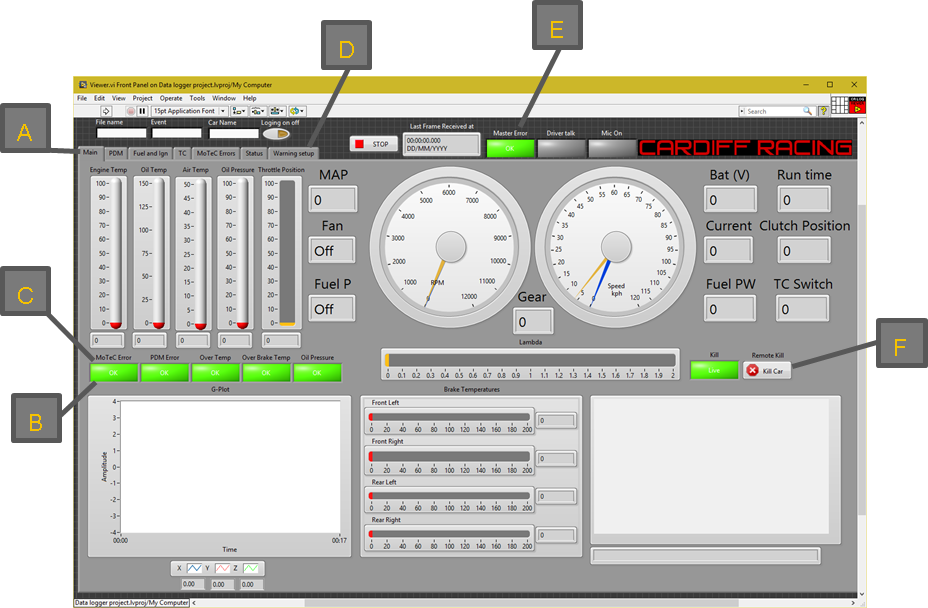
Figure 9 - User Interface main tab
In order to make sure the person looking at the data does not miss anything important, a warning system was also implemented on the main tab (B). For example, there are 43 MoTeC errors that could occur, but would not be viewable as they are in the MoTeC errors tab. To work around this problem since an error is Boolean data (true or false), a logical ‘OR’ was used to assess on the 43 errors so that if one of the errors where true the output of the ‘OR’ will be a true. This can then be wired to an indicator on the main tab, called MoTeC error (C).
Warning value limits were also setup in the warning setup tab (D) so if engine temperature, oil temperature, oil pressure or brake temperature go over a threshold limit an indicator will be lit. Finally, a master error indicator was used that will light up if MoTeC error, PDM error, over temperature, over brake temperature or the oil pressure exceed the threshold limit. This is at the top of the program so that it is always visible no matter what tab is currently being viewed (E).
A remote kill button (F) is also on the main tab; this allows the operator to remotely turn off the engine of the car if required. To stop accidental use of this button, a yes/no popup message is used.
Wireless Hardware
In order to increase the wireless rang of the system additional hardware was required. One option would be to design a custom communication system designed for this application. However due to the additional complexity and cost for custom hardware and possible licencing (for frequency use) this was not an option.
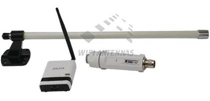
Based on this, off the shelf wireless hardware was used, focusing on using reliable and well established IEEE 802.11n commonly known as Wi-Fi. Exploring options available for long ranged Wi-Fi applications most products are aimed at people with Caravans, Boats, Yachts, Mobile homes. These products are designed for people who would like to connect to Wi-Fi networks from a long distance i.e. a caravan connecting to available Wi-Fi from a clubhouse across a field.
A bundle deal was specified and purchased as shown in Figure 10. It has everything required for the project; a large high gain 9dB Omni-Directional antenna and USB Wi-Fi dongle (wifi-antennas.co.uk, 2015). This would suit the trackside monitoring station side of the system where size and mass was not an issue. It also came with a small and compact Wi-Fi access point which was suitable for implementation into the car. The overall cost for the bundle was surprisingly inexpensive just under £100, which was far lower than the cost involved in the developing a custom wireless protocol and channel.
There final design can be seen in Figure 11, this is manufactured using selective laser sintering (SLS) 3D printing from polyamide.
As can be seen an attempt has been made to fully export the SLS 3D printing process. A number of features demonstrate this such as:
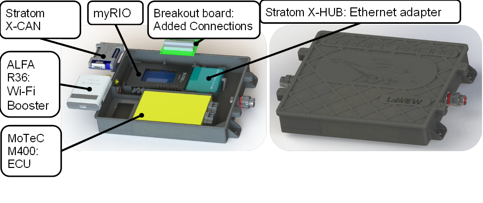
Figure 11 - Packaged electronics box
Further addiction sensors could be added such as tire temperature and pressure monitoring, and many more possible sensors. However, a rational should be applied to this not to add unnecessary extra weight.
Another area for further infestation is that of the wireless channel used. The current system using a Wi-Fi network going point to point. However, this could be replaced with a longer range custom wireless option or also another alternative, a mobile data connection (4G) could also be used expanding the range anywhere with a mobile signal.
The system aimed to make itself easy use when looking at the transmitted data. Using user interface elements like tablature menus and warning based indicators.
Finally, data can be logged for long periods while also being in one location. Having the ability to record data in the manner will certainly help with performance through quantitative design.
