- Document History
- Subscribe to RSS Feed
- Mark as New
- Mark as Read
- Bookmark
- Subscribe
- Printer Friendly Page
- Report to a Moderator
- Subscribe to RSS Feed
- Mark as New
- Mark as Read
- Bookmark
- Subscribe
- Printer Friendly Page
- Report to a Moderator
Contact Information
Competition Year: 2016
University: Sheffield Hallam University
Team Member: Jonathan Hird (2016)
Faculty Advisers: Dr Alan Holloway
Email Address: jonathan.hird@student.shu.ac.uk
Country: UK
Project Information
Title: A Reliable, Traceable and Scalable Embedded Building Monitoring System
Description: Development of an embedded building monitoring system (BMS) to monitor a number of environmental parameters including temperature and pressure as well as calculating energy and power usage of a building. The developed system incorporates a number of embedded technologies and protocols including WiFi, I2C, Real-Time and FPGA based code.
Products Used
- LabVIEW 2015 SP1
- myRIO
- Digilent SPI Breakout board for myRIO
- LabVIEW myRIO toolkit
- LabVIEW myRIO High-Throughput Toolkit
- LabVIEW Electrical Power Suite
- LabVIEW Report Generation Toolkit
- Data Dashboard
The Challenge
Building Management/Monitoring Systems (BMS) are becoming a standard of modern large scale building designs. There are many forms of BMS, typically the most common and simple BMS would be one that would come integrated with a large system, for example a heating, ventilation and air conditioning (HVAC) system which in turn has its own reporting and control software.
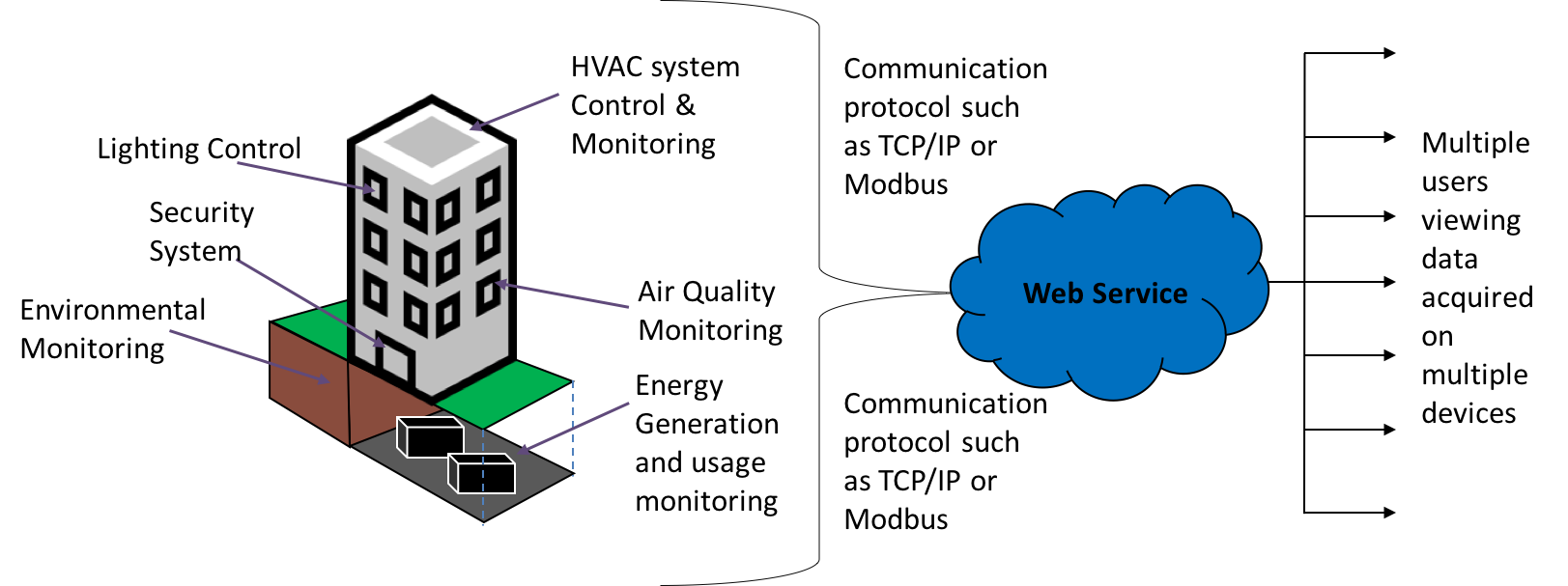
Figure 1 - A diagram of a typical BMS system
During initial research, it became apparent that these systems (specifically the system used at Hallam) can be seen as slightly disjointed in the fact that there is no long term reporting system other than for costing electricity, also the sensing can be seen as inconsistent by using multiple different protocols to different control/monitoring systems then feeding to multiple software packages pipelining into the 'host' BMS software.
These considerations led to this project whereby primary aim was to produce an embedded system to remotely condition monitor a set number of environmental and energy usage parameters in a building/room at Sheffield Hallam University. The system was specified to be able to monitor and log a number of parameters in a headless manner as well as providing adequate reporting to the user over a long history of data.
The Solution
The BMS system follows a simple process of data acquisition, data process and visualise/log the data, this coupled with the flexibility of the LabVIEW environment and the combination of protocols and features of the myRIO such as wireless connectivity, I2C and FPGA have led to the BMS system fulfilling the brief of a truly reliable, traceable and scalable building monitoring system.
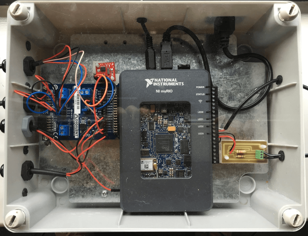
Figure 2 - BMS in its enclosure
At the heart of the BMS is the myRIO which facilitates a deterministic Real-Time environment for operation of all system code. The RTOS coupled with the flexibility of the Zync SoC means interaction between onboard FPGA & RTOS is seamless and easy to adapt on the fly. For the RTOS code, I have implemented a Queued Message Handler Architecture to provide a scalable, easy to debug framework to build the application around.
The Real-Time code itself is responsible for acquiring data on the MXP Ports from a number of I2C sensors, pulling data from FPGA based sensors and then collating and scaling this data into a traceable TDMS file format which is saved to an external memory stick connected to the myRIO. The code also provides SMTP reporting at pre-defined times of operation to send daily BMS reports as well as important technical system information to an administrator. The Real-Time code serves as the core of the BMS not only for DAQ & reporting but also as the host of the Shared Variable Engine Network for the system and an embedded web server host, allowing external devices to read/write data to and from the RIO both VIA Network shared variables as well as an XML based web service.
As well as the RIO code, the system incorporates a host application that can be run on any PC on the network via a bundled installer. The host application itself is the main User interface for the system due to the RIO running headless & with no interactive execution the host application provides read/write functionality via the shared variable network for visualization and customization to system parameters on the RIO. The host application combines a queued message handler architecture with Object Oriented Programming practices, this architecture style is based around using a single OOP class and provides encapsulation of references and data types to be able to pass this information easily between parallel loops, coupled with an actor framework based error handler the system architecture is robust, very easy to debug and scalable, the general architecture can be seen in Figure 3.
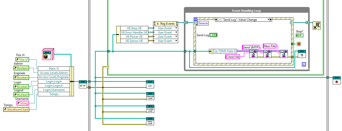
Figure 3 - OOP/QMH Architecture
There are 3 main screens on the host application, the main one being the general UI (Figure 4) that shows all acquired data in real time, the other two screen are accessible via an encrypted login system in which different credentials provide access to the admin screen and engineering screen. The host application also performs a redundancy logging operation, creating copies of TDMS logs to a defined folder on the PC as well as providing a separate optional SMTP execution that can be activated manually or automatically at pre-defined times. In addition to this functionality, report generation is also available, the application uses the report generation toolkit to collate a range of data points and associate them with bookmarks contained in a pre-made Word template (Figure 5).
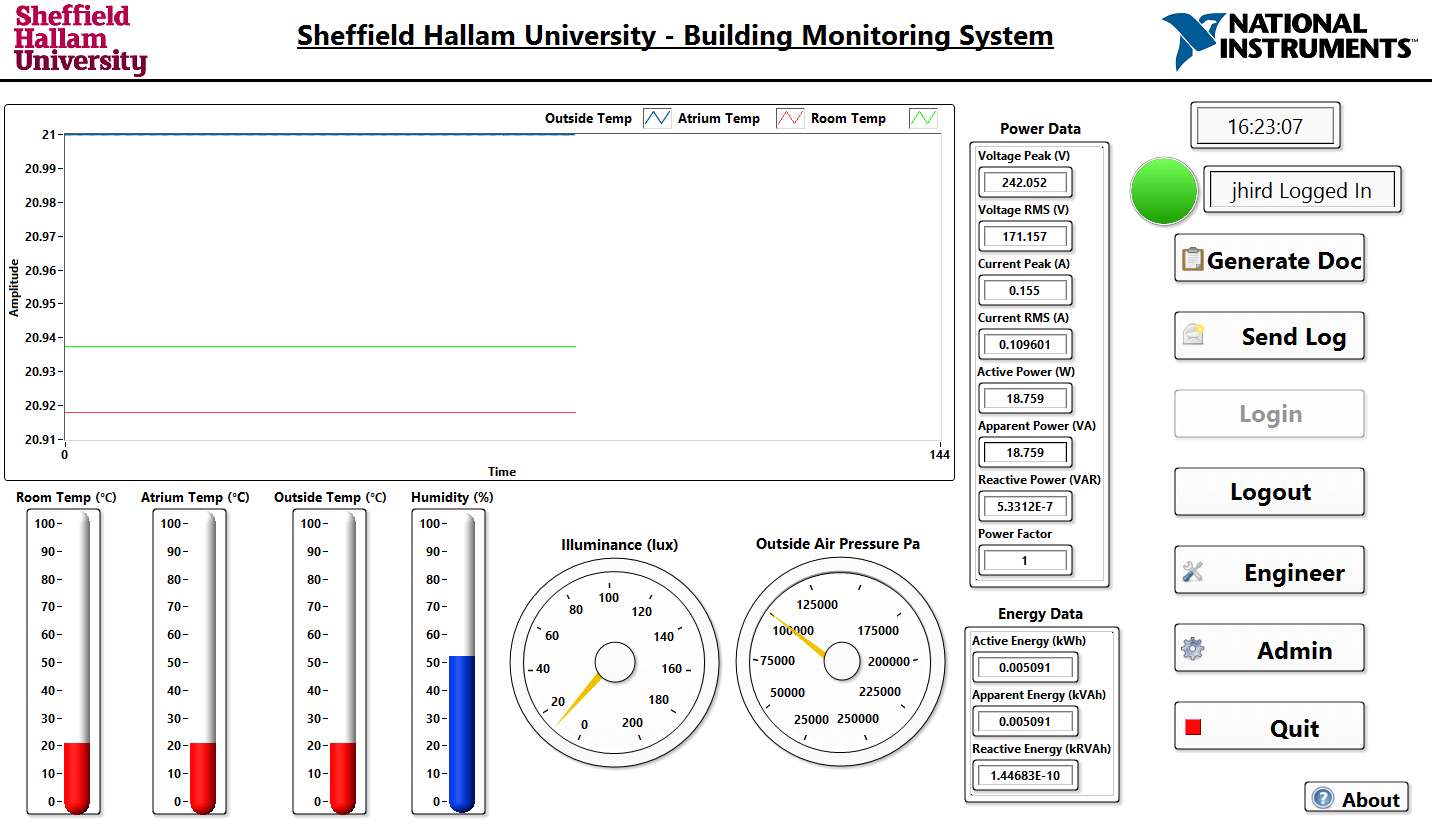
Figure 4 - Host Application UI
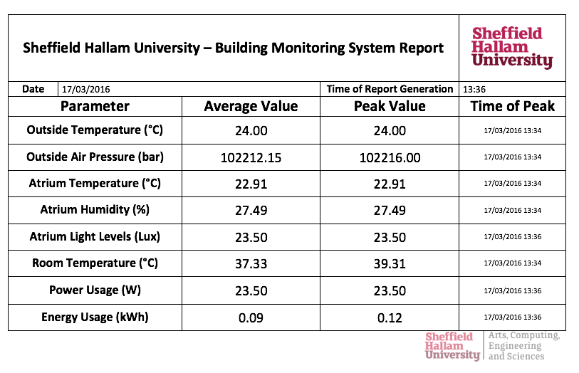
Figure 5 - Example Report
The Admin and Engineer screens provide 2 core functions:
1) Admin of login credentials
2) Viewing of system data such as memory, errors and heartbeats of the system
Both screens solve the issue of lack of system visibility when the myRIO is operating headlessly and can be seen in figure 6.
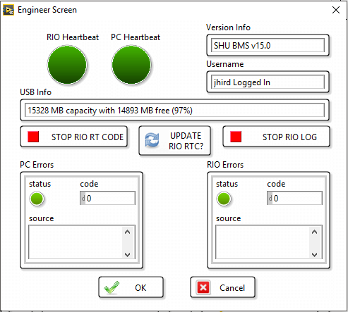
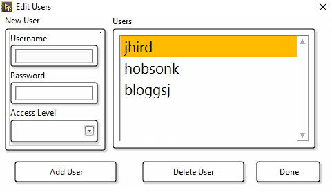
Figure 6 - Engineer & Admin Screens
Typically embedded applications incorporate some kind of mobile interface, in this application this is provided through a tablet based application running on National Instruments Data Dashboard. By connecting to the shared variable network via Wi-Fi, the application can monitor all acquired data as well as control execution of the RIO code remotely via a stop button. In general, the application is simplistic and can be viewed via 3 separate screens:
Environmental Screen - Providing live data of key sensor information
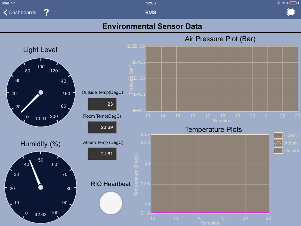 Figure 7 - Environmental Screen
Power/Energy Screen - Showing current Power and Energy Usage in the building
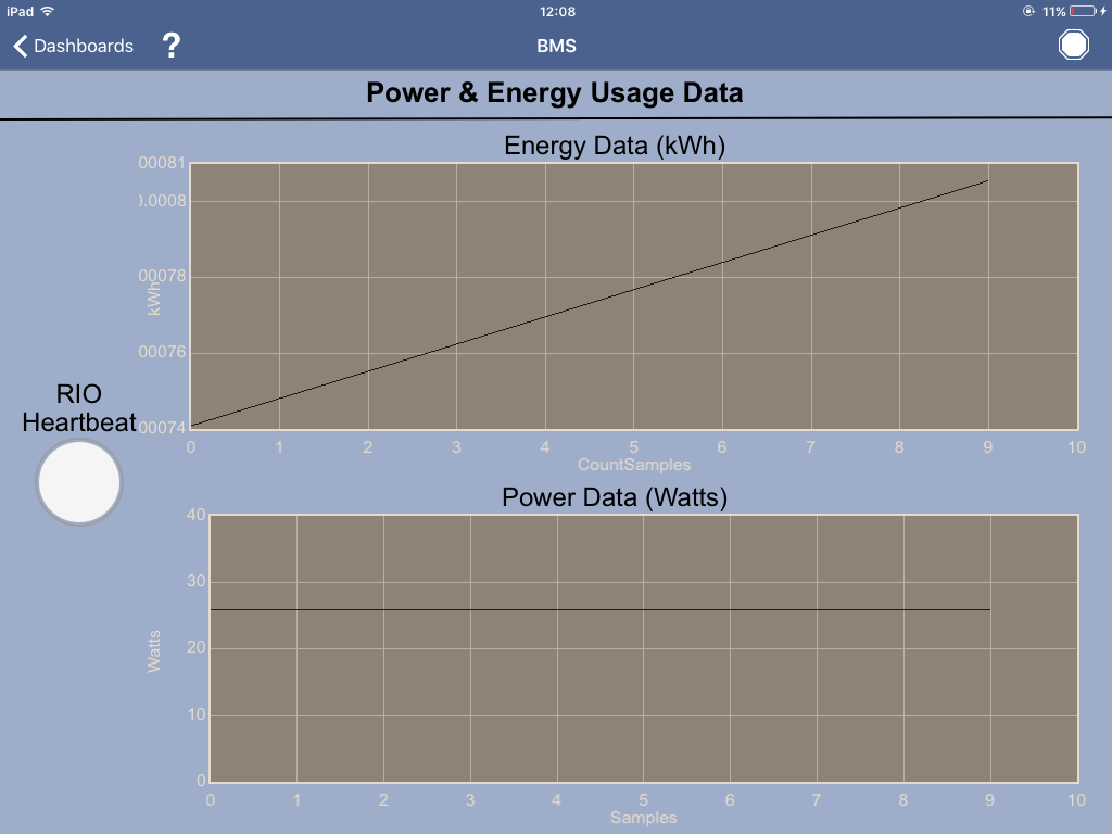 Figure 8 - Power/Energy Screen
Engineer Screen - Showing key system data similar to the engineer screen on the main application
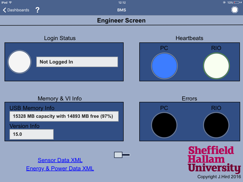 Figure 9 - Engineer Screen
This functionality extends the capability of the system, meaning that data can be viewed on the move in a simple, low cost application in your pocket!
Overall, the application can be seen as a fully functioning BMS that took around 25 weeks to complete from initial research and software architecture designs all the way through to a complete system in an enclosure that has been unit tested and soak tested for a 9 hour period. In the future, it would be ideal to incorporate wireless sensing into the system via a low cost method such as XBee radios as well as incorporating multiple embedded devices representing different buildings and therefore adapting the framework to collate multiple streams of data from multiple buildings. Feedback from the facilities services at Hallam were positive, they saw how 'easy' such a system could be built with a central UI & reporting interface that only included the most useful data.
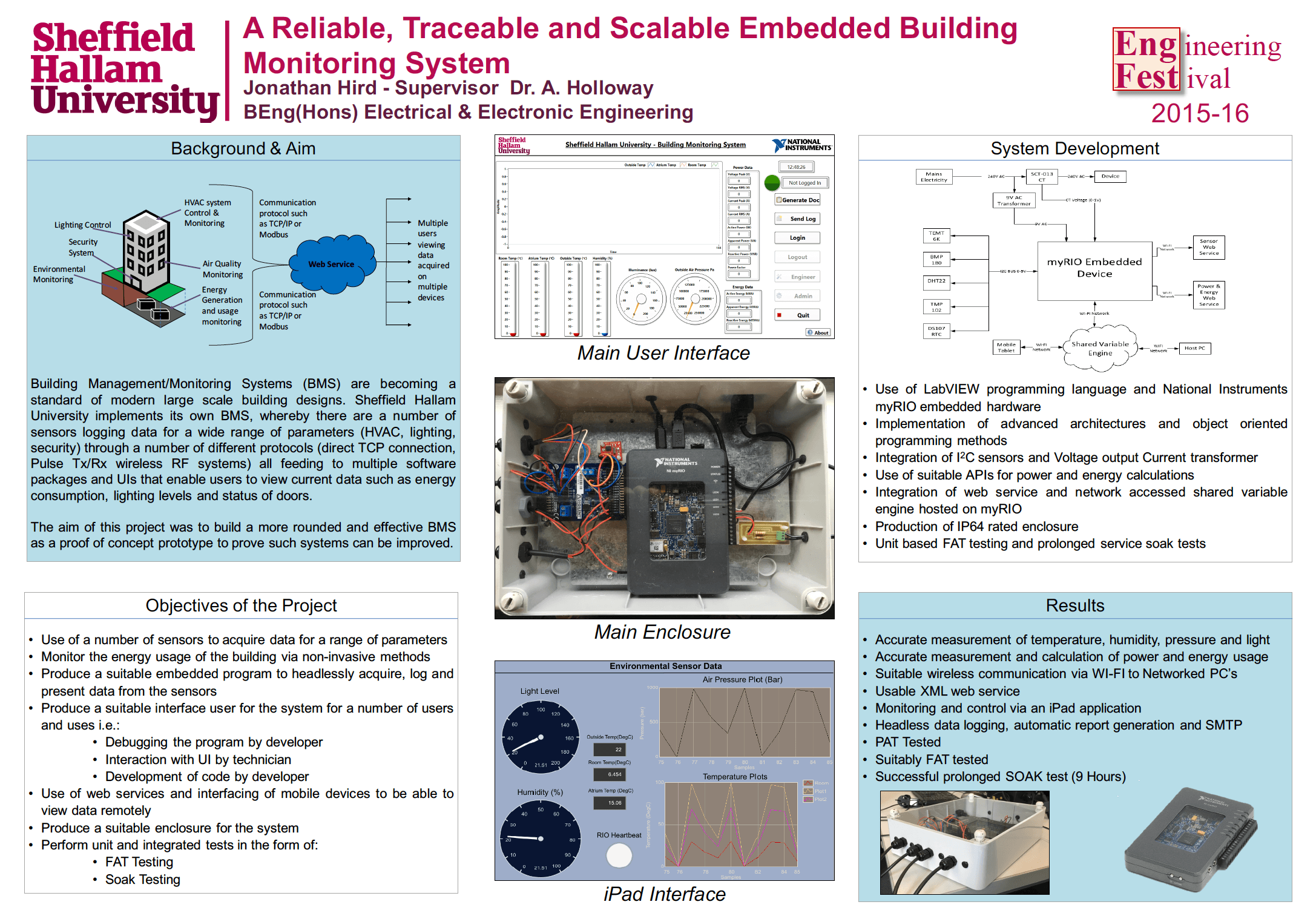
Poster
- Mark as Read
- Mark as New
- Bookmark
- Permalink
- Report to a Moderator
An interesting project, thank you for sharing your work!
Did you enounter any difficulties getting the SMTP email feature to work with myRIO? I have tried both the "Send Email" Express VI as well as the lower-level SMTP VIs -- works fine when running on the PC host, but throws the error "LabVIEW could not verify the authenticity of the server" when running on the myRIO target (I'm using the Gmail SMTP server).
- Mark as Read
- Mark as New
- Bookmark
- Permalink
- Report to a Moderator
Great Project, I would suggest with regards to using GMAIL I have had issues in the past with Linux based targets usually an issue with SSL. I would try one of the other ports listed at this link. https://support.google.com/a/answer/176600?hl=en
Certified LabVIEW Architect, Certified Professional Instructor

- Mark as Read
- Mark as New
- Bookmark
- Permalink
- Report to a Moderator
Thanks for the link, this gave me additional options to consider. After some additional digging, I believe that I do not have a TLS certificate installed on the myRIO. I discovered that adding the "Config TLS" VI with its "verify server" terminal set to "false" allows the application to successfully send email via the Gmail server.
For best security, then, it seems that the server certificate should be installed on myRIO so that the server's authenticity can be verified, but I have yet to find instructions on how to do that.
- Mark as Read
- Mark as New
- Bookmark
- Permalink
- Report to a Moderator
Thanks for the feedback!
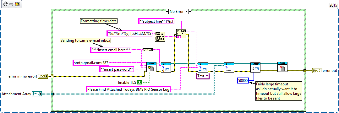
Thats my basic structure on the RIO. Port 587 with TLS eneabled is the only confguration i could get to work on the RIO. I think I got an SSL setup working too but it was flakey with attatchments.
Certificate wise, i believe authenticenty is derived deep down in the API via username/password entry (I may be wrong). For myself the only SW on the RIO i specifically installed for SMTP was SMTP with SSL support and SSL support for LV RT, the ports were the biggest issue.
Hope you get it working & feel free to use my snippet!
Cheers
Jono
- Mark as Read
- Mark as New
- Bookmark
- Permalink
- Report to a Moderator
Thanks for your suggestions and code snippet with the timestamping code which helped me to trace the root of the problem, too! The error message "LabVIEW could not verify the authenticity of the server" gets thrown when the myRIO system date is too far away from reality. Some experimentation showed that everything works fine as long as the myRIO system date is no more than 12 days into the past and less than 71 days into the future. When my myRIO power cycles its date is about 14 months into the past.
Thanks again for your help!
Ed
- Mark as Read
- Mark as New
- Bookmark
- Permalink
- Report to a Moderator
Hi Ed
Yes, one of the downfalls of the myRIO is the fact that it has no onboard RTC!!! therefore it can't keep a system time between system downtimes.
My solution for this was to use a I2C based RTC, specifically the DS1307 (as there is a community library for this). It only takes one configuration using the API and it will keep its time via the 3V battery for decades!
Let me know if you need any help!
Cheers
Jono
- Mark as Read
- Mark as New
- Bookmark
- Permalink
- Report to a Moderator
Great, thanks for the tip, will definitely keep this in mind. The community library code you referenced has a funny comment, too -- the cautionary note about the "Y3K" bug!
