From Friday, April 19th (11:00 PM CDT) through Saturday, April 20th (2:00 PM CDT), 2024, ni.com will undergo system upgrades that may result in temporary service interruption.
We appreciate your patience as we improve our online experience.
From Friday, April 19th (11:00 PM CDT) through Saturday, April 20th (2:00 PM CDT), 2024, ni.com will undergo system upgrades that may result in temporary service interruption.
We appreciate your patience as we improve our online experience.
University and Department:UC Berkeley
Team Members: Emily Cheng, Keaton Chia, Vivian Chu, Jason Cuenco, Terry Liu
Faculty Advisors: Trung Tran
Primary Email Address: kchiarcher@gmail.com
Describe the challenge your project is trying to solve.
This project, dubbed 'Self Piloted Aircraft Rescuing Remotely Over Wilderness, or 'S.P.A.R.R.O.W', was a joint effort between two students in ME 135: Introduction to microprocessor-based mechanical systems and three students in EECS 149: Introduction to embedded systems. The goal of this project was to create a self-piloted unmanned aerial vehicle (UAV) in the form of a helicopter platform. The idea and inspiration of this project stemmed from a UAV search and rescue competition known as 'UAV Challenge 2009', held in Queensland, Australia. The goal of this competition is to develop and fly a remotely controlled airborne delivery system that can drop an emergency package to a lost bushwalker - 'Outback Joe'.
We chose to make our delivery system in the form of a '3D' helicopter for extended maneuverability and accuracy, as well as to provide a challenging framework to demonstrate proportional control and sensor feedback. Of the different types of RC helicopters,"3D" helicopters are the most difficult to fly. Simpler ones such as coaxial (have two rotors spinning in opposite directions) or fixed pitch (main rotor blades have a fixed pitch and thus only have four degrees of freedom) helicopters can easily achieve a stable hover. "3D" helicopters, on the other hand, are able to perform aerobatic maneuvers such as rolls and inverted flight by dynamically changing each rotor blade pitch independently. This gives the helicopter six degrees of freedom (up and down, side to side, forward and backward, roll, pitch, and yaw).
Describe how you addressed the challenge through your project.
This project's goal is to create a fully autonomous and tether free helicopter. This means that the circuitry and code must be robust enough to withstand small impacts. Also the helicopter must have enough power to accommodate all hardware without significant performance changes. In addition, unlike similar projects, this helicopter is to be a completely embedded system. In the past, other projects have either included a base station controlling the helicopter (computation moved to an external computer) or custom built mini-computers. Both of these have increased computational power, however they are more costly and less practical.
It was realized early on that a solid testing environment would be needed in order to safely fly the helicopter. However, it was important to mimic the degrees of motion that a real helicopter would experience in order to accurately complete the project. This took out the option of merely strapping the helicopter down to a solid object to prevent it from taking off.
As a result a test stand was developed to allow for the maximum degrees of movement. Most of the stand material ended up being standard PVC piping and joints due to the material’s high strength, low cost, and relatively low density. We took a few of the parts to the machine shop to modify the parts to match our needs.
The main components used to make the base included a cross piece that connected to five PVC pipes. Since the standard piece only connects to four pipes in a flat cross formation, we had to bore a hole in the center of the piece so that we could connect a pipe perpendicular to the base plane.
By doing that, however, the fifth pipe introduced an end cap that extended past the cross piece and the four pipes forming the base was no longer flat on the ground. In order to counter this, we connected joint pieces to the end of each of the four base pipes to make it level. This square base with a center extension upward served to prevent the whole stand from tipping over in any direction. After figuring out how to stabilize the base, we went on to make the telescoping part of the stand by inserting a smaller pipe inside the perpendicular base pipe. We had a string connecting the top of the telescoping pipe to the bottom of the base to prevent the telescoping effect from going too far (i.e. preventing the inner pipe from leaving the outer pipe). The smaller, telescoping pipe had a spherical bearing inserted at the top, and a bolt and several nuts connected the helicopter platform to the bearing. This allowed the helicopter enough rotational freedom for roll, pitch, and yaw while also preventing it from going so far in any of those directions as to strike something with its blades.
After all of this was done, the stand seemed ready to be used, but we soon ran into the problem of a bad take-off affecting our flight performance. The helicopter would start very slanted due to the freedom supplied by the spherical joint, but we fixed this problem by adding a double layer of orange safety cones to serve as a level plane for the helicopter platform to land on. This ensured the helicopter a normal, level take-off which would better simulate a real ground take-off. The flex from the cones also provided a little cushion for a hard landing which we originally planned to accomplish using springs inside the PVC pipes.. (Figure 1)
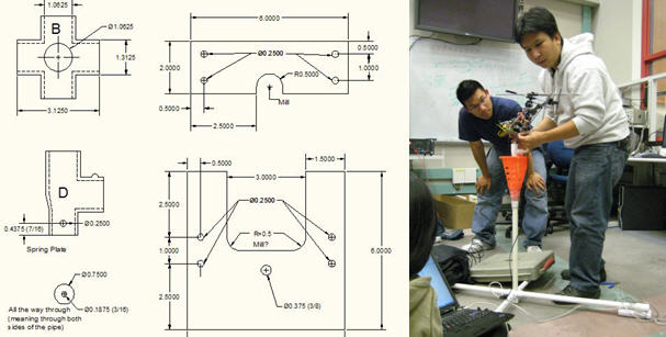
Figure 1: Test stand CADs and final stand with helicopter mounted.
Hardware
The RC helicopter for this project uses CCPM or cyclic and collective pitch mixing. This means that both the cyclic controls (roll and pitch) are combined with the vertical controls in an algorithm that affects the pitch of the rotor blades. This type of helicopter is challenging because it is not inherently stabilizing. However, it does allow for more degrees of freedom than other types of RC helicopters. In fact, the helicopter can fly upside down and perform other complex aerial maneuvers. In addition, CCPM helicopters have a quick control response, allowing for faster stabilization.
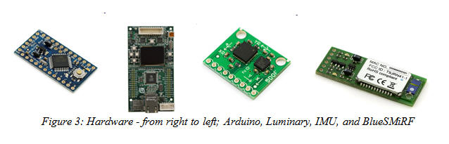
The orientation of the helicopter was determined using the IMU (inertial measurement unit) combo board. This board outputs analog measurements of acceleration along the x, y, and z axes, as well as the angular velocities around the x and y axes.
Our main microprocessor was the Luminary Evaluation board which would perform gain scheduling, control, mixing, and communication using LabView. A second processor, the Arduino (ATmega 328), acted as our fail-safe by taking servo commands from either the Luminary or RC receiver. (Figure 2)
Continual serial communication with a distant ground station was accomplished with the use of a BlueSMiRF Bluetooth modem.
A custom PCB was also designed so that more components (IMU, Magnetometer, Arduino, and Ultrasonic Range Finder) could be integrated and easily mounted onto the helicopter. It would also reduce the overall weight and thus extend flight time. (Figure 3)

Algorithms and Formal Models used
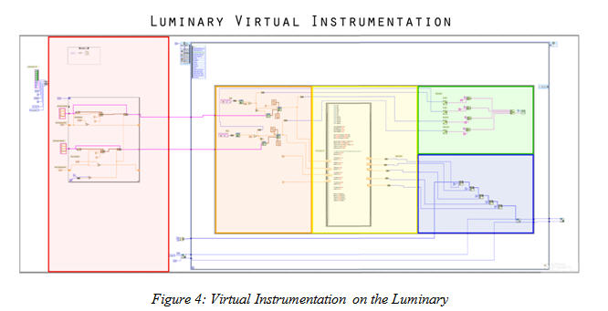
Embedded LabView VI
The Embedded LabView VI is split into four main parts: Gain Scheduling, Control, Mixing, and Communication. (Figure 4)
Gain Scheduling
In general, a proportional control works by first finding the difference between a given set-point (desired value) and the actual value. This difference, or error, is multiplied by a constant, Kp, to give a control output. Initial testing utilized a single Kp value, which gives a linear control response. When testing these settings a decent hover was accomplished. However, it would oscillate slightly and sometimes become unstable. This is because helicopter dynamics are actually non-linear. To account for this, gain scheduling was incorporated. This is an array of Kp values that correspond to error values. So as the error increases a higher Kp is used. This creates a non-linear response or a curve. To adjust the curvature, the start-point and step-size can be changed. The start-point is the first value of the array and the step-size is how much the gain increases with each step (Figure 5).
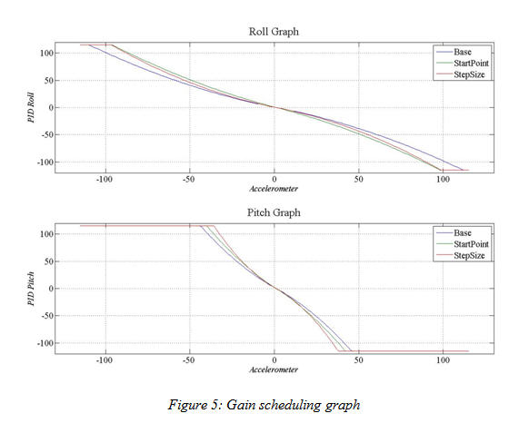
To reduce the amount of memory used, it was important that this array be created outside of our control loop so that it would only be made once. A flat sequence structure was also used so that the array would be made first before the control loop started. Rather than hard-code the array a for-loop was used to update all 115 values once a start-point and step-size was put in. This made it much easier to try different settings in order to fine-tune our system.
Control
In our case we wanted our helicopter to remain level which equates to an accelerometer value of around 560. This is scaled down to zero and our set-point is also set at zero. The reason for this scaling was so that if the helicopter tilted to the left (positive) or the right (negative), the absolute value of that change could be found and used in the gain scheduling which ranged from 0-115.
Both the accelerometer value and gain schedule are then passed into a PID VI. At first we tried different combinations of proportion, integral, and derivative gains, however in the end we used only proportional gains.
In order to see the how our controller was behaving, a simulation VI was made. The inputs for the gain scheduling could be easily typed in and after running a plot would be created that showed the controller's response. This made it much easier to see how set-point and step-size changes compared to previous settings.
Mixing
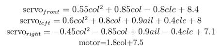
Mixing involves converting flight controls (pitch, yaw, roll, and collective) into output PWM’s that controls four servos and a motor on the helicopter. In the CCPM (cyclic/collective pitch mixing) system, the pitch, roll, and collective controls are all determined by the orientation of the rotor, which is regulated simultaneously by three servos. That is, for each servo, all the flight controls must be taken into consideration. CCPM involves mixing these signals and translating them into the three servo PWMs by using a series of equations. The actual algorithm was found experimentally by using an oscilloscope to find the PWM duty cycle output of each channel of the RC receiver at different values of RC controller joystick positions. These values were then fit to equations and coded into the VI. It was shown that changing the collective had a non-linear effect on the three servo’s positions, whereas pitch and roll were directly proportional to servo output. The following equations output servo PWM duty cycles and a motor duty cycle for different values of desired pitch (ele), yaw (yaw), roll (ail), and collective (col).
Communication
There were two different types of communication protocols used for the project: Serial Communication and I²C.
It was decided that in to order efficiently tune the gains required for stable flight, live data needed to be sent back from the Luminary to a base station (laptop computer). Information sent back contained accelerometer readings and PID values. Serial protocol was used for this transfer. On the embedded platform, serial communication ports were created and configured to send a string of data separated by tab deliminators and labeled with a single ASCII character in front of the value: X, Y, I, J.
The Arduino is capable of outputting up to eight software PWMs, all that is required is each of the duty cycle values. These values are sent from the Luminary in a five byte array through I²C. The Luminary acts as a master and signals to the Arduino that it is sending five bytes. The Arduino acts as the slave and receives data whenever Luminary indicates that data is available.
Base Station VI
A base station computer runs a VI that continually receives data from the helicopter via Bluetooth. Streamed data from the Luminary is parsed based on the prefixed ASCII character and placed into a single array for each set of data. This data is then displayed on charts with accelerometer data and the proportional control, and are continually updated for real-time monitoring from a distance. (Figure 6)
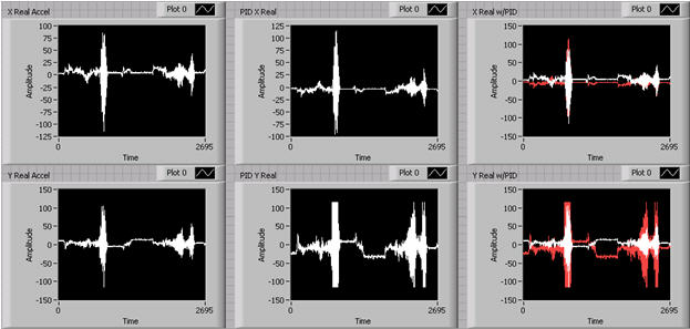
Figure 6: Capture of real-time data from IMU
When enough data has been collected for that "flight", the VI then stores the data into an ASCII file where it can later be reloaded in Signal Express and analyzed at a later date.
Embedded Arduino Code
The Arduino code is split up into three main components: Control, Communication, and Pulse Width Modulation/Servos.
Control
Because of the dangers of flying a helicopter completely autonomously, a manual switch was developed. On an RC Helicopter controller, there exists a toggle switch also known as a "Kill Switch". When this switch is on, the throttle normally outputs a PWM duty cycle value between 5.7%-9.3%. However once it is flipped, this switch "kills" the PWM controlling the throttle by setting it at a duty cycle of 5.0%.
To take advantage of this switch, the input channel of the throttle PWM was fed into an input pin of the Arduino. By polling with an update() function that looped continuously, the Arduino would be set into either "AUTO" or "MANUAL" mode.
Communication
We implemented I²C on the Arduino by using built in libraries, more specifically the Wire library. This library included a function that would join the Arduino with the Luminary through a common chosen 7-bit address. Once joined, the wire library would then listen for an event with function onReceive(). Given a function handle, onReceive() calls the function once data is available. The Wire library uses interrupts to notify the program when data is available to read. The code is shown below:
Wire.begin(0xA0); // join I²C bus with address 0xA0
Wire.onReceive(receiveEvent); // register event
receiveEvent() grabs values one byte at a time as well as does any other necessary calculations once data is received as shown below:
void receiveEvent(){
{
while (Wire.available())
{
if (state == AUTO) {
servo1 = Wire.receive() * 20; //receive one byte
...
Pulse Width Modulation/Servos
The built in function pulseIn() was used to read the duty cycle of a PWM going into a digital input pin. pulseIn() would return the servo value between 1000 and 2000, 1000 being the minimum servo duty cycle, 6%, and 2000 the maximum, 10%. To ensure that pulseIn() would not get interrupted by I²C, whenever servo values were read, interrupts were disabled, thereby making the code atomic. A threshold was also added to decrease jitter. This is seen below with servo1:
int read_Ch(int pin)
{
servoValue = pulseIn(pin);
if (servoValue == 0){
read_Ch(pin); //recursively calls until a true servo values
} else { //is returned as opposed to 0 if pulseIn times out
return servoValue;
}
}
...
noInterrupts(); //disable interrupts
int temp = read_Ch(servoIn1);
interrupts(); //enable interrupts
if (abs(temp-servo1) > 50){
servo1 = temp;
}
...
The main library used to write servo values was ServoTimer2. This external library written for Arduino was used because it allowed for better resolution and more accurate values as opposed to the general PWM library that were not made for servos. A simple function write(servoValue) was all that was needed to output a steady PWM with the correct 50Hz frequency.
Challenges
General Embedded
As expected, a substantial amount of challenges were encountered over the course of this project. Some general issues included certain limitations of the Luminary microcontroller board. We initially intended to run all of our code through the board, but it provided only four analogue to digital converters (ADC) when we needed six. We worked around this problem by incorporating an Arduino board into the system, which would handle additional input from our sensors.
Since this is a mobile platform, weight and balance also became an issue. Helicopters such as this are unable to fly properly when too much weight is loaded onto their frame, so we had to limit what we placed onto the frame. Likewise, the choice of using an onboard microcontroller system caused a limitation regarding memory, computational power and runtime speed. This required us to constantly optimize our code in order to have it run properly on the embedded system.
Gain Scheduling
Testing the gain scheduling on the computer worked smoothly. However, problems arose when trying to import it to ARM. When testing on the Luminary in debug, the outputs of the gain scheduling array incorrectly read zero. It was found that clusters and arrays do not update properly through debug mode.
Finding the proper set of gains is a huge challenge with controls. At first it was difficult to understand how the gain settings related to actual helicopter behavior and how gain schedule adjustments would impact that performance. Having only one Kp value resulted in relatively stable flight within a small range of accelerometer values, but unstable behavior when the helicopter tilted outside of that range. To try and fix this the accelerometer range was broken up into four different regions and Kp values were assigned to each. This helped improve performance, but introduced jumps in the controller output as it transitioned to each region. In order to smooth out the controller Kp gains were assigned to each accelerometer value (115 in total) which gave a smoother output curve. This resulted in much better helicopter performance over the entire range of its movement.
When tuning for the appropriate gain, the helicopter would at times hit points of oscillation where the PID would compensate incorrectly how much was needed to stable the helicopter. This resulted in the helicopter wildly oscillating until it landed. Shown below in Figure 7 is the data captured on the Base Station VI and reloaded in Signal Express.

Figure 7: Signal Express data. Note the clipping of the red PID values.
The white graph shows that accelerometer value steadily increasing as the helicopter starts to oscillate. The red graph shows the PID values trying to compensate for the oscillation, but instead maxing out at incorrect times and causing the oscillation to propagate.
Control
A major challenge in control was the use of floats. We tried to minimize the use of floats as much as possible and converted to smaller data types whenever we could.
Tuning a control system is a difficult task and often takes many test runs to find the correct set of gains. RC helicopter batteries have a very limited flight time (15-20 minutes) and long charging time (6-8 hours). This made it difficult to get a lot of test flights in. Having the control simulation allowed us to make better estimations of the gains so that we could get the most out of our test flights.
Mixing
Using matrix operations to control the servo PWM duty cycles was highly recommended. However, attempts to use matrices in the LabVIEW embedded module resulted in non-functioning VI’s. This was most likely due to memory and operation limitations. Through trial and error, it was found out that LabVIEW embedded does not support mathscript or formula nodes.
Communication
One of our main challenges with communication was just being able to implement the many protocols. While embedded serial communication was well documented, I²C was not and it took much trial and error to even get a simple string sent.
Bluetooth also provided many limitations with its range. When using the standard BlueSMiRF, data could only be reliably captured within 2-3 feet of the helicopter. To bypass this problem, a BlueSMiRF with an antenna had to be used instead. This resulted in an increase of 10 feet of reliable data. Furthermore, the default baud rate for the BlueSMiRF was 115k. This ended up being too fast of a rate and resulted in data being lost or crashed VIs once the buffer overflowed. Once we realized this, decreasing the baud rate to 57,600 resulted in a much more stable transfer.
I²C also had a few quirks that needed to be ironed out. When using a FTDI cable to upload code and power the Arduino, I²C would work flawlessly. However, once powered externally without the FTDI USB cable, it would suddenly not work. After scanning schematics for standard FTDI cables, it was determined that pull-up resistors were built into the FTDI cable and needed to be added to our circuitry in order for I²C to function correctly. Furthermore, I²C implemented through Arduino's library was blocking. Before this was realized, there was much confusion as to why the Luminary VI would suddenly "stop working".
Pulse Width Modulation/Servo
Initially the Luminary was to write a 50 Hz PWM to the servos. However, LabView only has a clock resolution of milliseconds whereas microsecond resolution was needed to properly control the servos. To overcome this, a PWM was created by first turning on a digital pin, waiting a given time via while loop in C, and then turning off the pin. This was problematic though because it could not be done in one timed loop as it would run late. However, when two timed loops were created there were problems with passing data between them. The control loop tried to pass duty cycle values via local or global variables to the PWM loop. It was found that both local and global variables are not thread-safe. This caused issues with reading and writing to the variables. Attempts were made to fix this by changing the offset between the loops as well as their priorities, but eventually the Arduino was substituted.
When implementing the manual switch to read and echo PWM values, a jitter was introduced to the servo that did not exist before. After much testing, it was determined that Arduino's I²C library implemented I²C such that it would use interrupts. This caused reading servo values to be interrupted before they could return a result. This created a "jitter" in the servo when in manual mode. To fix this, interrupts had to be disabled in the correct areas as specified earlier to create interrupt safe atomic code.
Results
Over the course of this project, we were able to accomplish a stable hover with our helicopter platform both on and off the test stand. When flying on its own, the helicopter was able to safely hover within a 15 meter radius. This was made possible through the design of a rigorous data feedback system, which allowed the platform to sense its orientation in real-time and properly adjust its servos to compensate for imbalances. In order for this system to operate at an appropriate speed, we also employed simulated control of our gains. Another essential accomplishment achieved in this project was the proper communication of our various hardware components, which included serial communication through Bluetooth as well as Integer Integrated Circuit or I²C protocol for communication between our Luminary and Arduino microcontroller boards. (Figure 😎
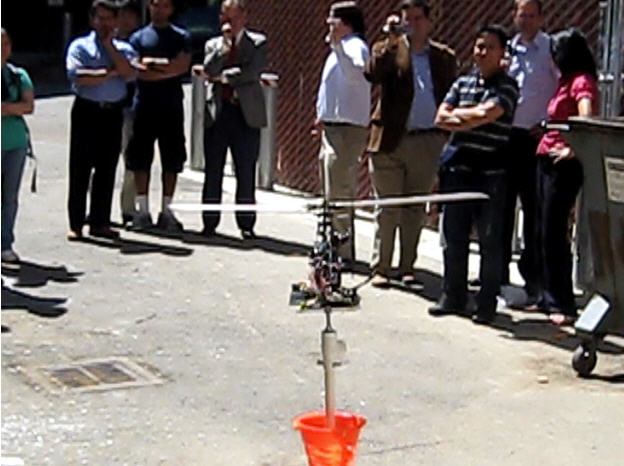
Figure 8: Picture of system functioning on test stand.
Along with our accomplishments, we also encountered several things which did not end up working and were scrapped. This included running PWMs directly from LabView, as the overhead was too great while running the rest of our code, resulting in unstable output. Local and global variables were bypassed by moving most of our VI code into larger loops. Finally, two-way serial communication for live gain value changing was scrapped in favor of one way communication with manual flashing of the luminary board.
For future plans, we intend to add an ultrasonic range finder to the bottom of our helicopter platform so that it will be able to automatically control its throttle as well. This implementation would utilize a similar proportional gain feedback system to have the helicopter adjust the motor so that it can hover a given distance above the ground.
Additionally, we intend to implement a Kalman filter, magnetometer and GPS system to allow the helicopter to localize itself. This would allow the system to truly hover in place and not drift from its original position. More importantly, this implementation will allow the helicopter to navigate given GPS waypoints, as well as provide us with live feedback through GPS tracking software running on our base station.
Team Dynamic
In order distribute the work amongst our team, we devised a list of essential topics or tasks to focus on and had each member choose two to take responsibility for. This ensured that there was at least two people working on one particular element of the project (Aside from Test Stand design). The following is a basic breakdown of each of our assignments:
This setup worked relatively well where each of us managed to follow through with the assigned task. There was however some switching around as we progressed through the project and met unforeseen challenges.
Key Concepts
The following are several key concepts from the course which we used extensively to accomplish the goals in our project.
Proportional Control and System Simulations: In order for a helicopter to successfully stabilize itself autonomously, a feedback control system was needed. A proportional feedback control system was successfully implemented in this project. Furthermore, we successfully created a simulation of gain to accelerometer values to develop a control output curve.
Concurrency: There were many instances of concurrency in this project. On the Luminary proportional control is being applied to both the pitch and the roll. After mixing I2C and serial are performed.
For the C code running on Arduino, I2C is running concurrently with the servo update functions. We used class concepts relating to atomic code and interrupts in order to smoothly integrate I2C with servo reading functions.
Interfacing with the physical world: Though our code often worked in theory, it had to be calibrated to match the actual hardware. When the control first ran several servos had to be re-calibrated so that "zero" equated to the swash-plate (part of the rotor that changes blade pitch) being level.
Data Flow: In the LabView VI it was important to set the order of operations. For example, communication ports had to be initialized before control and communication writing happened. This was also essential for reducing the amount of memory used. Arrays were all initialized before the control loop so that they would be created only once.
Real Time: Timing of each of our processes was very important. The PWM must be a consist 50Hz or else the servos would jitter. All three servos must also be updated simultaneously due to the nature of CCPM helicopters which rely on two or more servos moving at once to move the helicopter. Also the control must be running at a proper speed so that stability is maintained. Communication must also be timed well so that there no information overflow or interrupt issues.
hi ,
this is jyothibasu,i have completed my diploma in mech engg and now pursuing my btech.we all of our friends are palnned to built a helicopter (like the one used in 3 idiots)
so please help me with ur suggestions. (my email address: jyothibasu.kalyanapu710@gmail.com)
