- Document History
- Subscribe to RSS Feed
- Mark as New
- Mark as Read
- Bookmark
- Subscribe
- Printer Friendly Page
- Report to a Moderator
- Subscribe to RSS Feed
- Mark as New
- Mark as Read
- Bookmark
- Subscribe
- Printer Friendly Page
- Report to a Moderator
digsys-06: State Machines for FPGA-Based Controllers
Introduction
State machines, also known as finite state machines, play a vital role as controllers for digital systems. State machines belong to the sequential circuit family, and therefore contain a memory element to store the machine state as well as combinational logic to determine the state progression and output values.
This article briefly reviews state machine hardware and state diagrams, describes how to implement and verify state machines in LabVIEW, and presents a practical example of a digital system controlled by a state machine implemented with LabVIEW FPGA – a garage door opener that includes a safety mechanism for obstructions. The following movie clip shows the finished project in action:
State Machine Background
A state machine contains a state register memory element, a next-state decoder, and output decoder combinational logic circuits. A LabVIEW feedback node and case structure directly implements the state machine. The following video reviews the state machine hardware layout and shows its LabVIEW implementation:
State diagrams specify the intended behavior of a state machine. The next video introduces state diagrams and presents the notation used in this article; topics include the relationship of the states and transitions to the state machine hardware, unconditional and conditional transitions, self loops, wait states, and unused states:
Implementing State Machines in LabVIEW
The LabVIEW state machine implementation was briefly mentioned in an earlier video. The next video describes the basic layout of the state machine in LabVIEW in more detail as follows: (1) state register implemented with a feedback node, (2) case structure for a combined next-state decoder and output decoder, and (3) mechanism for a system reset:
Numerical values for states become confusing for larger numbers of states, and complicate modification and maintenance of the state machine when states need to be added or removed. The LabVIEW enumerated data type associates a text label with numerical values, and makes the state machine self-documenting and easier to maintain as described in the next video:
Now that the basic technique to implement a state machine has been developed, consider the following moderately complex state diagram:

This state diagram does not accomplish anything in particular, but rather illustrates a variety of state transitions likely to emerge for practical designs. The following video details the translation of this state diagram into LabVIEW, and also demonstrates manual testing of the finished state machine:
IMPORTANT NOTE: The while-loop samples the inputs (front-panel controls) and sets the feedback node output at the beginning of each iteration before executing the rest of the diagram. The inputs are therefore only sampled once per clock cycle, effectively placing a register in front of the inputs, like this:

The register effectively delays the inputs for one clock cycle. A one-cycle delay causes no problem for inputs created by “human interface devices” such as pushbuttons and switches, since they operate very slowly compared to the system clock rate. However, anytime individual clock cycles become critical, as in manual testing of a state machine or when the state machine interacts with another device at the same clock rate, the delay is confusing at best and causes system failure at worst. Once known and understood, the single-cycle delay simply becomes part of the design methodology.
State Machine Verification Techniques
State machines must be verified to ensure that they behave according to the state diagram specification. Fortunately the graphical nature of LabVIEW eases review of the VI G code itself. However, a proper verification applies an input sequence and compares the actual state and output sequence to the expected sequences.
A slow loop rate allows the state machine to be tested with no fuss, at least when getting started. The previous video included a simple verification by pressing the front-panel pushbuttons at the proper times.
Diagrams with complex transition conditions quickly become difficult to test manually like this. The debugging tools in LabVIEW come in handy here; see the next video to learn how to use the “highlight execution” feature to watch data moving through the block diagram, and also how to set break points to pause execution at the end of each clock cycle:
Example: Garage Door Opener System Controller
A modern garage door opener contains a good deal of complexity, including features such as optical obstruction detection for safety, over-torque detection to prevent motor burn-out, variable motor speed for a quick door open and slower closing, and decryption of the remote control signal for security:
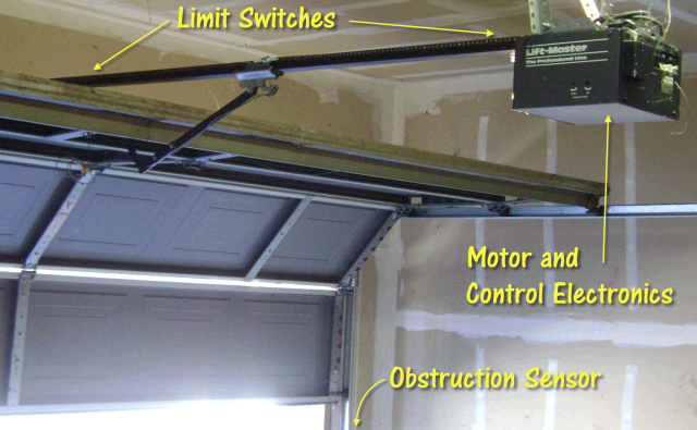
Image Credit: https://commons.wikimedia.org/wiki/File:Garage_door_opener.jpg
In this example, a state machine serves as the system controller for a simplified garage door system that includes an obstruction sensor and limit switches to indicate when the door is completely closed and completely open. The motor is controlled with a pair of signals to indicate “move door up” and “move door down.” The following video briefly describes a simulation model for the garage door originally developed on the desktop and then modified for eventual use on the FPGA:
The Xilinx Spartan-3E Starter Kit FPGA development board serves as the hardware platform for this project; refer to the links at the end of this document for the LabVIEW project file, as well as an equivalent project file for the National Instruments Digital Electronics FPGA board.
Pushbuttons emulate the remote control clicker and the limit switches, and the discrete LEDs show the position of the garage door. The pushbuttons must be debounced to ensure that only a single press is detected by the controller. Sampling the pushbutton signal at a 5-millisecond interval or longer provides a simple yet effective way to ignore switch chatter for many projects. Enclosing the pushbutton FPGA I/O nodes within a while-loop structure paced at 5 milliseconds works well here.
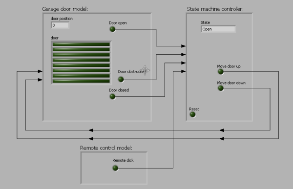
The complete garage door controller system requires three subsystems: the state machine controller, the garage door model, and the pushbuttons, and is diagrammed here:
The state machine controller behavior is captured by the state diagram shown below:

The controller requires seven states, and generally implements the following behavior: if the door is stationary, clicking the remote control starts motion in the opposite direction; if the door is moving, clicking the remote stops the door; an active obstruction sensor prevents door closing, and immediately reverses direction when the door is closing.
Each of the three subsystems operates at a different rate, and is implemented in a separate while-loop in LabVIEW. The garage door model is the slowest, operating at half-second intervals. The pushbutton switches are sampled at 5-millisecond intervals to ignore switch chatter and yet respond very quickly. The system controller operates the fastest with a 1-millisecond interval.
Note that the three while-loops operate simultaneously and in parallel. LabVIEW dataflow does not communicate information out of the loop via a wire until the loop terminates. However, each of the three loops become parallel hardware structures on the FPGA, and therefore should operate as long as the FPGA is powered. “False” constants wired to the Loop Condition terminal (the stop sign in the lower right of the while loop) create infinite loops. Consequently, global constants provide the means to communicate information between loops, and eventually become wire interconnections on the FPGA.
The following video walks through the FPGA-targeted garage door controller, and describes the global variable technique for subsystem interconnection in more detail:
Refer to the first video in this article for a real-time demonstration of the garage door controller operating on the FPGA board.
Conclusions
Digital systems designers rely on state machines to control, sequence, and coordinate the behavior of other digital subsystems to perform a useful activity. State diagrams translate easily into LabVIEW, and the enumerated data type provides self-documentation and ease of maintenance. LabVIEW debugging tools such as data flow highlighting and breakpoints simplify verification of the state machine, as well. The garage door opener system described in this article illustrates a practical example of a state machine serving as a system controller.
