Description
Description-Separate-1Introduction
I need to be able to log simple digital events from a remote or hazardous location.
To do this I decided to use a programmable Wireless Sensor Node to allow me to take low power measurements from remote locations.
I used the WSN-3202 and have had the counter running to 25 Hz. Using the LabVIEW for WSN Module we can use the DI notifications to detect when a rising edge happens.
Background
DI notificaitons are designed to let the LabVIEW code running on the node know when a rising or falling edge has occured. Once the event is detected in hardware
the "DIO Notification" case is fired and anything programed in this case is executed. This is a great feature if you want to detect the status of a machine quickly instread of
waiting until the next sample interval. Since notifications are implemented in software the frequency of the signals that can be detected are much lower than standard hardware counters.
There is a small amount of RAM on the nodes so if the sample case is executing and multiple events are detected there is a chance you will miss a digital event.
-- This example can detect signals that are ~25 Hz and below --
To see or characterize a digital waveform at a higher rate, you can sample faster on the DI lines in the "Sample" case and not use digital events.
Steps to Complete
To create the counter we need two VIs. One on the Node and a Windows VI to read the data from the node.
First the VI on the Windows system. The main part of the code is written just like you would expect to write code for a WSN node.
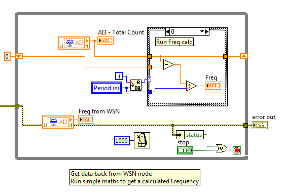
Windows based WSN code to read data from the node.
On the Node side of the equation, there is a bit more programming, but it is still relatively simple.
We need to modify the standard WSN VI to be a functional global variable (FGV) this allows us to run a feedback node to 'remember' a previous counter value.
We also need to register for value changes on a digital line to count the number of either rising or falling edges of a digital pulse.
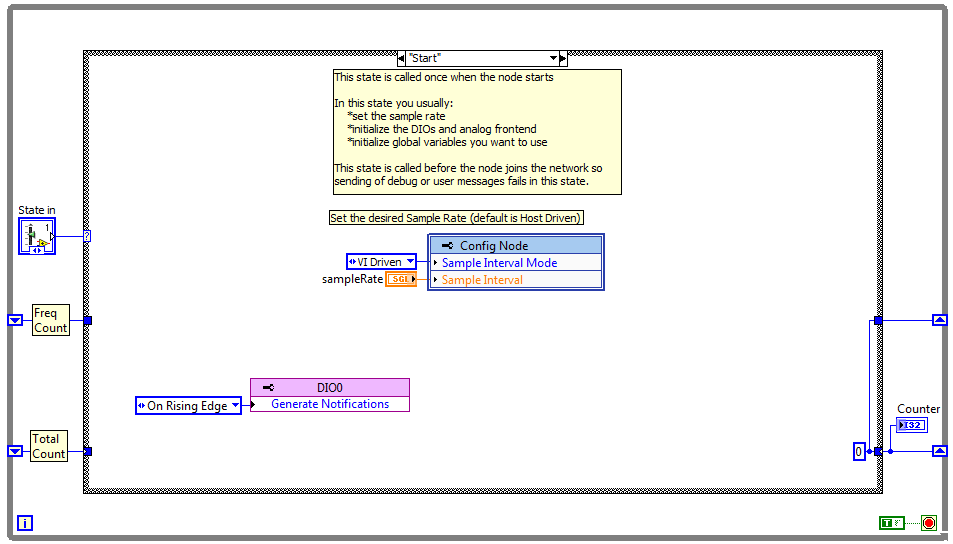
WSN VI showing the Start state with DIO notifications enabled. Also showing FGV architecture.
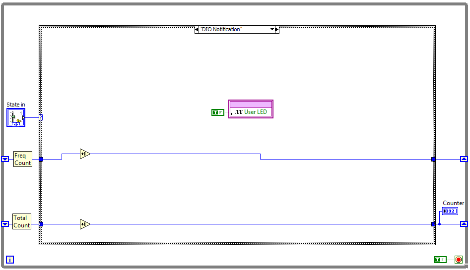
WSN VI showing the DIO Notification state and the increment of a couple of counters.
Additional Notes
This example require LabVIEW 2009 to open and run the VIs.
To build and deploy the WSN Node VIs you need to have the LabVIEW WSN Pioneer module installed on your system.
Under the WSN node there are 3 files and 3 build specs. The default build spec is the standard VI for the WSN node.
There is then a VI that just counts and still reads all IO pins on the node.
The Reduced Message VI, just does the count and sends the data out on AI2 and AI3 variables in LabVIEW, but the VI does not read any of the analogue pins in the system.
Description-Separate-2