From Friday, April 19th (11:00 PM CDT) through Saturday, April 20th (2:00 PM CDT), 2024, ni.com will undergo system upgrades that may result in temporary service interruption.
We appreciate your patience as we improve our online experience.
From Friday, April 19th (11:00 PM CDT) through Saturday, April 20th (2:00 PM CDT), 2024, ni.com will undergo system upgrades that may result in temporary service interruption.
We appreciate your patience as we improve our online experience.
How do I create a component in Multisim? Do I need a SPICE model? These are two common questions I hear from Multisim users. In this post I will be explaining how to use the Component Wizard to create a custom component in Multisim and I’m going to assume that you are new to the topic. So, let’s start with something easy: a simple transistor.
Let’s imagine that you are building an amplifier circuit and need the BCW30 transistor. This component is not included in the Multisim Database, so let’s create a custom component.
Here is what you need:
BCW30 datasheet. Includes general information about the component. For example: pinout.
BCW30 SPICE model. Necessary if you want to create a simulatable component. A SPICE model is a text-description of a circuit component used to mathematically predict its behavior.
SPICE models can be found in the manufacturer’s website. You can also use your favorite Web browser to locate them. In this example I will be using a SPICE model provided by Fairchild Semiconductor.
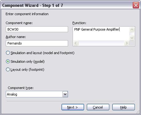
Step 1:
Let’s open Multisim and select Tools>>Component Wizard. In the first step you need to enter general information about the component (name, function); in this case you will create a simulation only component.
Step 2:
Enter the number of pins:
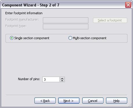
Note: Since you are creating a simulation only component, there is no need to enter footprint information.
Step 3
Multisim creates a default symbol for the component:
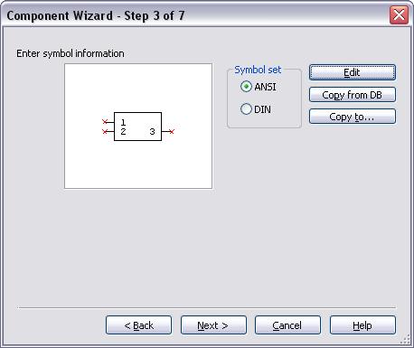
Here there are two options: you can click on the Edit button to open the Symbol Editor or, you can click on Copy from DB and select a symbol from the Multisim Database. In this case it will be easier and faster to copy a symbol (PNP transistor) from the database. Click on Copy from DB, this opens the Component Browser. Select the Transistors group, BJT_PNP family, select one of the generic symbols and click OK.

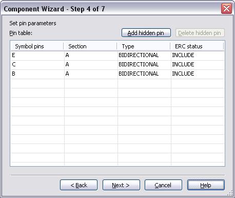
Step 4
Here is where you define the pin parameters, for example: power pin, input pin, and so on. Leave the default pin parameters as shown in the following figure:
Step 5
Here is the step where you need to enter the SPICE model. Click on Load from file and browse the file that you previously downloaded from the manufacturer’s website. 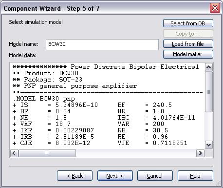
By the way, there are different file extensions for SPICE models: .lib, .cir, .llb, and so on. Ultimately this is a text file that you can open in a text editor.
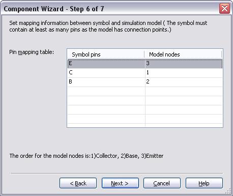
Step 6
This step is critical. Here you have to map the symbols pins to the model nodes. In this case Multisim is adding a note with the order for the model nodes, however, for more complex components you will have to get this information directly from the SPICE model and datasheet.
Step 7
Finally save your new component to your User or Corporate Database. You can also create a new Family for this component.
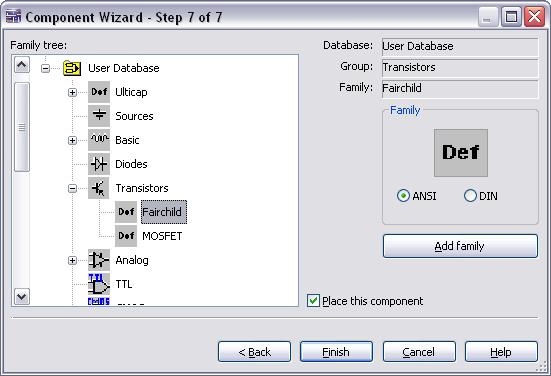
Click on Finish and place the component on the workspace.
Will your component work? Here is a quick test: place your component, a DC voltage source and GND, run the simulation. If you don’t get any errors that means Multisim understands the SPICE model.
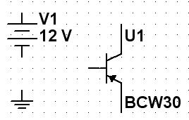
Of course, the best way to test your component is to build a test circuit.
The creation of a more complex component will be discussed in a later post, stay tuned!
Let me know your questions and/or comments.
Have a great day!
Fernando
You must be a registered user to add a comment. If you've already registered, sign in. Otherwise, register and sign in.
