-
NI Community
- Welcome & Announcements
-
Discussion Forums
- Most Active Software Boards
- Most Active Hardware Boards
-
Additional NI Product Boards
- Academic Hardware Products (myDAQ, myRIO)
- Automotive and Embedded Networks
- DAQExpress
- DASYLab
- Digital Multimeters (DMMs) and Precision DC Sources
- Driver Development Kit (DDK)
- Dynamic Signal Acquisition
- FOUNDATION Fieldbus
- High-Speed Digitizers
- Industrial Communications
- IF-RIO
- LabVIEW Communications System Design Suite
- LabVIEW Electrical Power Toolkit
- LabVIEW Embedded
- LabVIEW for LEGO MINDSTORMS and LabVIEW for Education
- LabVIEW MathScript RT Module
- LabVIEW Web UI Builder and Data Dashboard
- MATRIXx
- Hobbyist Toolkit
- Measure
- NI Package Manager (NIPM)
- Phase Matrix Products
- RF Measurement Devices
- SignalExpress
- Signal Generators
- Switch Hardware and Software
- USRP Software Radio
- NI ELVIS
- VeriStand
- NI VideoMASTER and NI AudioMASTER
- VirtualBench
- Volume License Manager and Automated Software Installation
- VXI and VME
- Wireless Sensor Networks
- PAtools
- Special Interest Boards
- Community Documents
- Example Programs
-
User Groups
-
Local User Groups (LUGs)
- Denver - ALARM
- Bay Area LabVIEW User Group
- British Columbia LabVIEW User Group Community
- Chicago LabVIEW User Group
- Egypt NI Chapter
- GUNS
- Houston Area LabVIEW Community
- LabVIEW - University of Applied Sciences Esslingen
- [IDLE] LabVIEW User Group Stuttgart
- LUGG - LabVIEW User Group at Goddard
- LUGNuts: LabVIEW User Group for Connecticut
- Madison LabVIEW User Group Community
- Mass Compilers
- Melbourne LabVIEW User Group
- Midlands LabVIEW User Group
- Milwaukee LabVIEW Community
- Minneapolis LabVIEW User Group
- CSLUG - Central South LabVIEW User Group (UK)
- Nebraska LabVIEW User Community
- New Zealand LabVIEW Users Group
- NI UK and Ireland LabVIEW User Group
- NOCLUG
- Orange County LabVIEW Community
- Ottawa and Montréal LabVIEW User Community
- Washington Community Group
- Phoenix LabVIEW User Group (PLUG)
- Politechnika Warszawska
- PolŚl
- Rutherford Appleton Laboratory
- Sacramento Area LabVIEW User Group
- San Diego LabVIEW Users
- Sheffield LabVIEW User Group
- South East Michigan LabVIEW User Group
- Stockholm LabVIEW User Group (STHLUG)
- Southern Ontario LabVIEW User Group Community
- SoWLUG (UK)
- Space Coast Area LabVIEW User Group
- Sydney User Group
- Top of Utah LabVIEW User Group
- Utahns Using TestStand (UUT)
- UVLabVIEW
- Western NY LabVIEW User Group
- Western PA LabVIEW Users
- Orlando LabVIEW User Group
- Aberdeen LabVIEW User Group (Maryland)
- Gainesville LabVIEW User Group
- LabVIEW Team Indonesia
- Ireland LabVIEW User Group Community
- Louisville KY LabView User Group
- NWUKLUG
- LVUG Hamburg
- LabVIEW User Group Munich
- LUGE - Rhône-Alpes et plus loin
- London LabVIEW User Group
- VeriStand: Romania Team
- DutLUG - Dutch LabVIEW Usergroup
- WaFL - Salt Lake City Utah USA
- Highland Rim LabVIEW User Group
- NOBLUG - North Of Britain LabVIEW User Group
- North Oakland County LabVIEW User Group
- Oregon LabVIEW User Group
- WUELUG - Würzburg LabVIEW User Group (DE)
- LabVIEW User Group Euregio
- Silesian LabVIEW User Group (PL)
- Indian LabVIEW Users Group (IndLUG)
- West Sweden LabVIEW User Group
- Advanced LabVIEW User Group Denmark
- Automated T&M User Group Denmark
- UKTAG – UK Test Automation Group
- Budapest LabVIEW User Group (BudLUG)
- South Sweden LabVIEW User Group
- GLA Summit - For all LabVIEW and TestStand Enthusiasts!
- Bangalore LUG (BlrLUG)
- Chennai LUG (CHNLUG)
- Hyderabad LUG (HydLUG)
- LUG of Kolkata & East India (EastLUG)
- Delhi NCR (NCRLUG)
- Montreal/Quebec LabVIEW User Group Community - QLUG
- Zero Mile LUG of Nagpur (ZMLUG)
- LabVIEW LATAM
- LabVIEW User Group Berlin
- WPAFB NI User Group
- Rhein-Main Local User Group (RMLUG)
- Huntsville Alabama LabVIEW User Group
- LabVIEW Vietnam
- [IDLE] ALVIN
- [IDLE] Barcelona LabVIEW Academic User Group
- [IDLE] The Boston LabVIEW User Group Community
- [IDLE] Brazil User Group
- [IDLE] Calgary LabVIEW User Group Community
- [IDLE] CLUG : Cambridge LabVIEW User Group (UK)
- [IDLE] CLUG - Charlotte LabVIEW User Group
- [IDLE] Central Texas LabVIEW User Community
- [IDLE] Cowtown G Slingers - Fort Worth LabVIEW User Group
- [IDLE] Dallas User Group Community
- [IDLE] Grupo de Usuarios LabVIEW - Chile
- [IDLE] Indianapolis User Group
- [IDLE] Israel LabVIEW User Group
- [IDLE] LA LabVIEW User Group
- [IDLE] LabVIEW User Group Kaernten
- [IDLE] LabVIEW User Group Steiermark
- [IDLE] தமிழினி
- Academic & University Groups
-
Special Interest Groups
- Actor Framework
- Biomedical User Group
- Certified LabVIEW Architects (CLAs)
- DIY LabVIEW Crew
- LabVIEW APIs
- LabVIEW Champions
- LabVIEW Development Best Practices
- LabVIEW Web Development
- NI Labs
- NI Linux Real-Time
- NI Tools Network Developer Center
- UI Interest Group
- VI Analyzer Enthusiasts
- [Archive] Multisim Custom Simulation Analyses and Instruments
- [Archive] NI Circuit Design Community
- [Archive] NI VeriStand Add-Ons
- [Archive] Reference Design Portal
- [Archive] Volume License Agreement Community
- 3D Vision
- Continuous Integration
- G#
- GDS(Goop Development Suite)
- GPU Computing
- Hardware Developers Community - NI sbRIO & SOM
- JKI State Machine Objects
- LabVIEW Architects Forum
- LabVIEW Channel Wires
- LabVIEW Cloud Toolkits
- Linux Users
- Unit Testing Group
- Distributed Control & Automation Framework (DCAF)
- User Group Resource Center
- User Group Advisory Council
- LabVIEW FPGA Developer Center
- AR Drone Toolkit for LabVIEW - LVH
- Driver Development Kit (DDK) Programmers
- Hidden Gems in vi.lib
- myRIO Balancing Robot
- ROS for LabVIEW(TM) Software
- LabVIEW Project Providers
- Power Electronics Development Center
- LabVIEW Digest Programming Challenges
- Python and NI
- LabVIEW Automotive Ethernet
- NI Web Technology Lead User Group
- QControl Enthusiasts
- Lab Software
- User Group Lead Network
- CMC Driver Framework
- JDP Science Tools
- LabVIEW in Finance
- Nonlinear Fitting
- Git User Group
- Test System Security
- Product Groups
- Partner Groups
-
Local User Groups (LUGs)
-
Idea Exchange
- Data Acquisition Idea Exchange
- DIAdem Idea Exchange
- LabVIEW Idea Exchange
- LabVIEW FPGA Idea Exchange
- LabVIEW Real-Time Idea Exchange
- LabWindows/CVI Idea Exchange
- Multisim and Ultiboard Idea Exchange
- NI Measurement Studio Idea Exchange
- NI Package Management Idea Exchange
- NI TestStand Idea Exchange
- PXI and Instrumentation Idea Exchange
- Vision Idea Exchange
- Additional NI Software Idea Exchange
- Blogs
- Events & Competitions
- Optimal+
- Regional Communities
- NI Partner Hub
-
 bikeron
on:
New International Rectifier Components in Multisim 14.0
bikeron
on:
New International Rectifier Components in Multisim 14.0
-
 giondoo77
on:
Creating Custom Arduino Shields With NI Multisim
giondoo77
on:
Creating Custom Arduino Shields With NI Multisim
- robo_Jeff on: Multisim Touch for iPad Now Available
-
doa4378
on:
New Models for Photovoltaic Cells in Multisim
- Mahmoud_W on: Connectors for NI 78xxR Multifunction RIO series in Multisim
- Mahmoud_W on: Search for Components in Digi-Key's Database While Building Your Circuit in Multisim
-
 BMac
on:
Ultiboard Mating PCB Design of the new NI GPIC Platform for Energy Applications
BMac
on:
Ultiboard Mating PCB Design of the new NI GPIC Platform for Energy Applications
-
Henry_Lavery
on:
Automotive Application: Hall Effect Sensor in Multisim
- GarretF on: LabVIEW-Multisim Co-Simulation with Variants and Hierarchical Blocks (Part 2)
-
Control_Dir
on:
Adding 3D Information in Ultiboard
Create a Component, Part 2: Using the Model Maker
- Subscribe to RSS Feed
- Mark as New
- Mark as Read
- Bookmark
- Subscribe
- Printer Friendly Page
- Report to a Moderator
Hi everyone! My name is Mahtab, and I am the newest addition to the NI Team. I am studying Engineering at the University of Toronto, and have some great experience using Multisim and Ultiboard. Throughout this summer I will be contributing to this blog on a weekly basis. My goal is to use my experience with simulation, circuit design and Multisim, coupled with my unique perspective as a student at the University of Toronto, to write helpful posts on how to be more productive when using our NI tools. I look forward to your feedback and thoughts! 
A few weeks ago, Fernando made a post that dealt with how to create a component based upon a SPICE model downloaded from the manufacturer’s website. But what do you do in the instances when a manufacturer has not (or cannot) provided a SPICE model for their product? Is it still possible to create a custom component?
Fortunately, this is possible in Multisim, and there are a few ways of doing it. One way is to create a SPICE macro model for an IC (a very good tutorial can be found here). Another way, which I will explain today, is to use the Multisim Model Maker, a seldom used tool in the product. Because the SPICE model created by this tool is basic, accuracy cannot be guaranteed. Nevertheless, it is a fast and easy way to create a simple SPICE model.
For this tutorial, I am going to create the TZX2V4A Zener Diode from Vishay (available at http://www.vishay.com/diodes/list/product-85614/). As you can see from the website, the simulation model is not available, but a datasheet is. With the values given on the datasheet, and only these values, we will be able to create our component. In just 8 simple steps (and about 5 minutes of work) we will create a custom diode!
Step 1:
From the toolbar, go to Tools>>Component Wizard. The Multisim Component Wizard will walk you through the steps of creating a component. Fill out Step 1 so it looks similar to Figure 1:
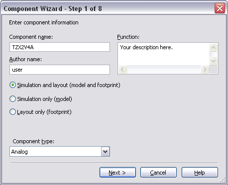
Figure 1 - Component Wizard Step 1
Click Next to go to Step 2, which asks for a footprint.
Step 2:
Click the Select a footprint button and then the Filter button and fill out the fields as shown in Figure 2. Note that you will need to click the Add row button to create each filter.
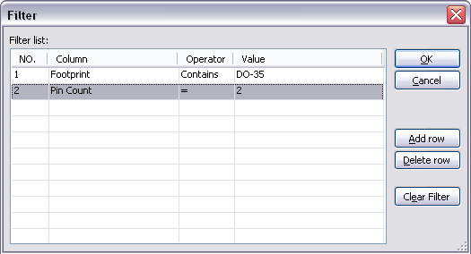
Figure 2 – Component Wizard Footprint Filter
Click Ok to go back to the footprint selection step. It should look similar to Figure 3.
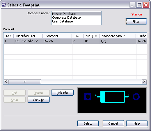
Figure 3 – Select a Footprint
Click Select to confirm the footprint, and you will be brought back to Step 2 of the Component Wizard. In our case, we are working with a Single Section Component, and the Number of pins is 2. Click Next.
Step 3:
Here, we specify a symbol. The default is the rectangle shown, but we are going to change the symbol so it actually looks like a Zener Diode. Click Copy from DB and select any Zener Diode from the Master Database (under the Diode group, Zener family), then click OK (as in Figure 4 below).
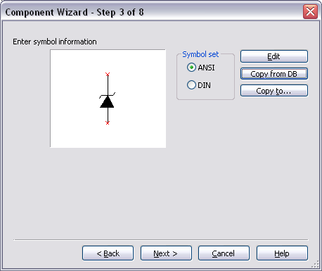
Figure 4 – Symbol Information
Click Next.
Step 4:
Accept the defaults and click Next.
Step 5:
Change the Footprint pins so that the symbol and footprint pins have the same mapping as in Figure 5.
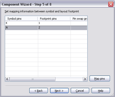
Figure 5 - Mapping information
Click Next.
Step 6:
In this step of the Component Wizard, we are asked for Model Data. If we had a SPICE model we could copy it here; since one is unavailable, however, we can simply use the Model Maker. Click the Model Maker button, and select Zener from the list. Click Accept.
Now, we can use the values from our datasheet to fill in the Electrical Characteristics and the Temperature Coefficient, Capacitance if that data is available. Fill in the appropriate values. In our case, it should look similar to the following image (based upon our datasheet):
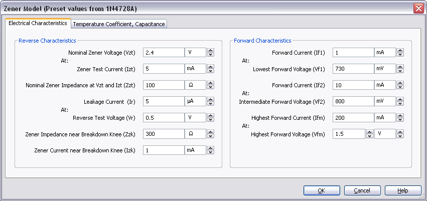
Figure 6 - Zener Model
Click Ok when you have filled in all the data. The values you enter may be different from the above image depending on which component you are creating.
Now we are back to Step 6 of the Component Wizard, and you can see that the Model data has been (magically) filled in. Change the Model name to TZX2V4A and click Next.
Step 7:
Accept the defaults and click Next.
Step 8:
Now we choose a location in the database for our new component. I am going to place it in the User Database, under Diodes. Click the Add Family button and call the family name Zener. Click Ok, select the Zener family you just created, and click Finish.
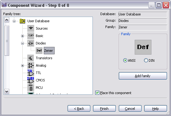
Figure 7 - Component Wizard Step 8
And there you have it – you have created a component using the Multisim Model Maker. You can now test your component by building a test circuit.
Thanks for tuning in!
Mahtab
You must be a registered user to add a comment. If you've already registered, sign in. Otherwise, register and sign in.
