From Friday, April 19th (11:00 PM CDT) through Saturday, April 20th (2:00 PM CDT), 2024, ni.com will undergo system upgrades that may result in temporary service interruption.
We appreciate your patience as we improve our online experience.
From Friday, April 19th (11:00 PM CDT) through Saturday, April 20th (2:00 PM CDT), 2024, ni.com will undergo system upgrades that may result in temporary service interruption.
We appreciate your patience as we improve our online experience.
Hello Circuit Designers,
I wanted to highlight some add-on tools that enable a high-level simulation of Analog to Digital Converters (ADC) in the Multisim SPICE environment.
ADCs are used everywhere where an analog signal needs to be processed in the digital domain, such as audio/video applications, control and monitoring, software defined radio, instrumentation, and many other. Simulating an analog front-end in Multisim is valuable to optimize the signal conditionning circuitry before building a prototype, however, it is also important to learn how these signals will look like in the digital domain and perform different measurements on them.
The ADC add-ons are behavioral models developed in NI LabVIEW and compiled to be used within Multisim. Among 70 other tools, they are available for download at the Multisim custom instruments and analyses community. For these specific instruments, make sure you have the LabVIEW Run-Time Engine 2010 installed, and follow the setup instructions here.
The models mainly focus on the modeling of the front-end of the ADC parameters (such as the capacitive input impedance), yet not involving some of the complex calculations at the digital back-end of the ADC (such as I2C transformation).
Here are some screenshots from the ADC measurement instrument.
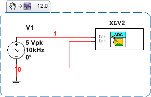
Multisim Schematic:
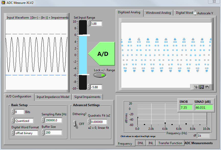
Input and digitized analog signal output, ADC configuration and frequency response are shown at the bottom:
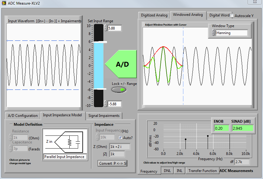
Windowed analog signal and modeling of the ADC input impedance (note also the dynamic input range):
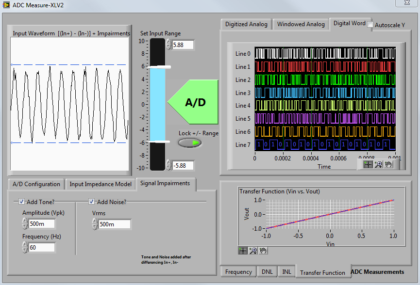
Output digital word and the transfer function measurements after adding some signal imparements:
Non-linearity measurements at the bottom:

You must be a registered user to add a comment. If you've already registered, sign in. Otherwise, register and sign in.
