From 04:00 PM CDT – 08:00 PM CDT (09:00 PM UTC – 01:00 AM UTC) Tuesday, April 16, ni.com will undergo system upgrades that may result in temporary service interruption.
We appreciate your patience as we improve our online experience.
From 04:00 PM CDT – 08:00 PM CDT (09:00 PM UTC – 01:00 AM UTC) Tuesday, April 16, ni.com will undergo system upgrades that may result in temporary service interruption.
We appreciate your patience as we improve our online experience.
11-23-2011 09:24 PM - edited 01-16-2017 12:10 PM
Update January, 2017: You can find the latest version of the floating point state-space and transfer function solvers in the master power electronics IP and examples library. See the Guide to Power Electronics Control Application Examples and IP Cores for NI GPIC for download instructions, folder locations and more.
Update Mar. 9, 2015: The state-space solver is now available as an example for the graphical floating point toolkit, which greatly simplifies development by eliminating the need to scale the state-space coefficients to appropriate fixed point word lengths. The floating point state-space solver is "universal" in the sense that it can simulate any state-space model (up to 9x9) without needing to recompile the FPGA or normallize/adjust coefficients-- making it more powerful and easier to use. A floating point transfer function solver is also available. Both the floating point state-space and floating point transfer function solvers are available as speed optimized (> 1 MHz) and resource optimized (> 100 kHz) versions. To learn more and download the toolkit and solvers, see whitepaper A and whitepaper B.
Update Jan. 16, 2013: The software installers and code for this RCP and HIL system are being updated. In the mean time, you can find an archived version of the state-space HIL reference design here. This code matches the application note below. The HIL reference design is NOT currently included in the latest versions of the Power Electronics Design Guide Code.
Just getting started? View a new introductory tutorial video on FPGA-based HIL simulation here.
This reference design project demonstrates the power electronics design flow from desktop testbench applications, to co-simulation, rapid control prototyping (RCP) and hardware-in-the-loop (HIL) simulation using the LabVIEW graphical system design toolchain.
In-Depth Tutorials and Code Walk-Throughs
Part 1 Tutorial: Use Testbench Apps to Verify before You Compile
Part 2 Tutorial: Use cosimulation to verify your HIL simulation math and calculate switching losses
Part 3 Tutorial: Execute your control code and HIL simulation in real-time to the verify the control system
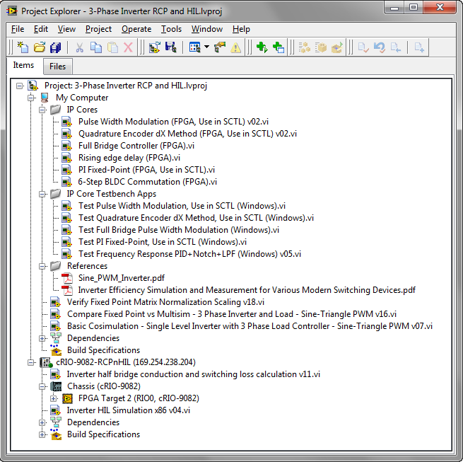
LabVIEW Project
Here's a summary of what's in the project:
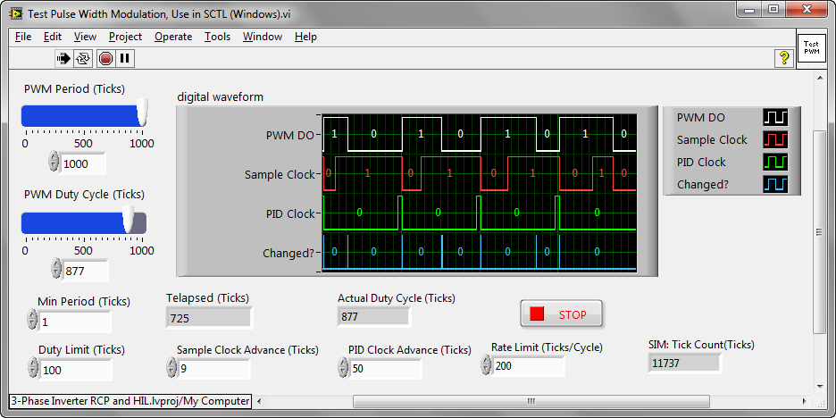
IP Core Testbench Applications: A variety of testbench applications for the LabVIEW FPGA IP Cores included in the project. Always define the functional requirements for each element of your control algorithm before beginning development. Then create a testbench application that tests and verifies that the IP Core meets your requirements. Whenever changes are made, re-run the testbench to verify the code is working before using in co-simulation or compiling to the FPGA target. (The NI Unit Test Framework tools can facilitate this.)
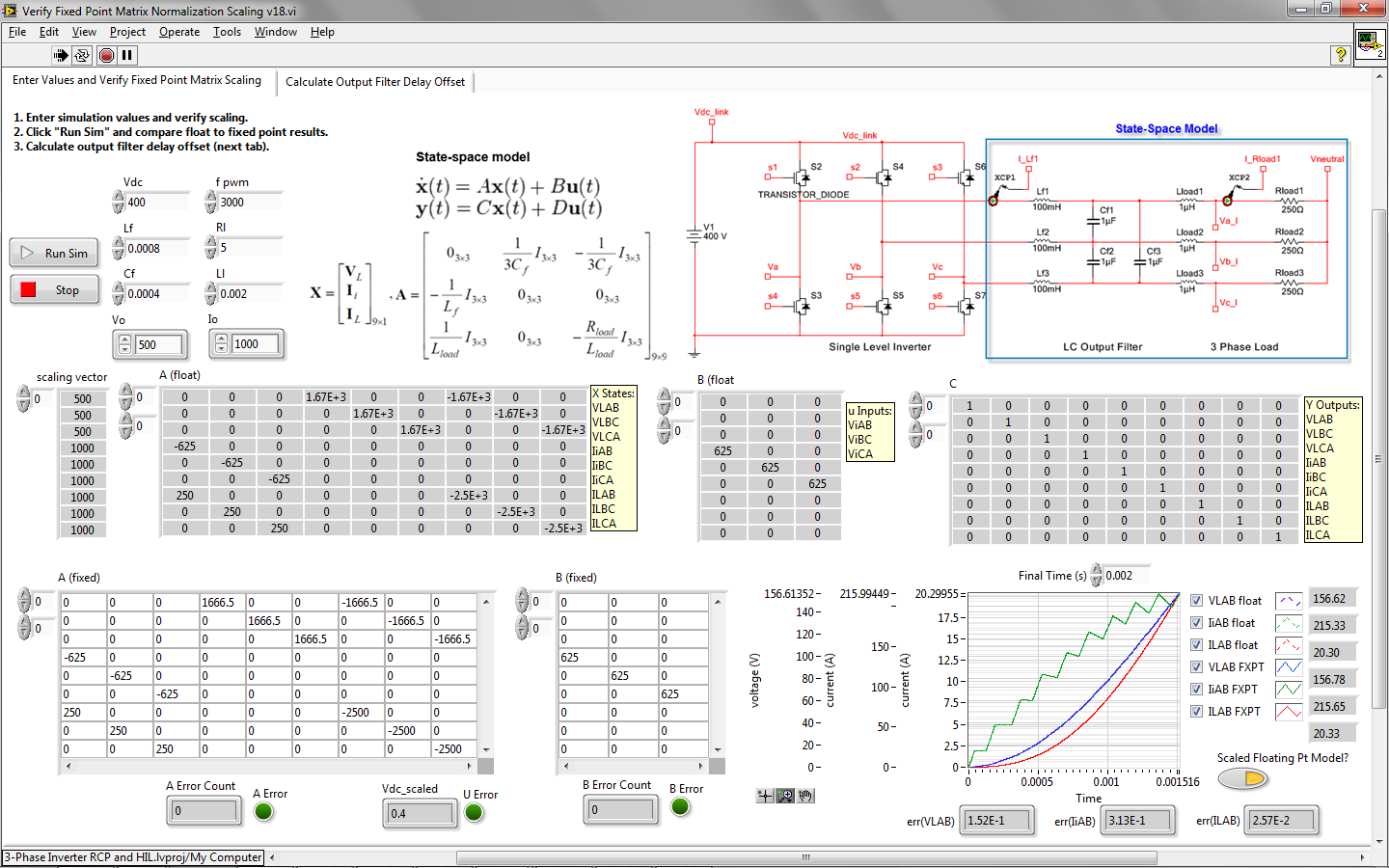
Verify Fixed Point Matrix Normalization Scaling v18.vi: Shown below. Run this and adjust the Vo and Io scaling so that your state-space system maps to the correct fixed point word lengths for simulation in the FPGA. Once you have selected your scaling with no errors on A, B, or U, then click the Run Sim button to run a simulation using both the floating point and fixed point versions of the state-space model. Verify that the error is sufficiently small at the end of the simulation run. Then click on the "Calculate Output Filter Delay Offset" tab and note the Output Filter Phase Offset (pi) value to use for your LabVIEW FPGA based control system.
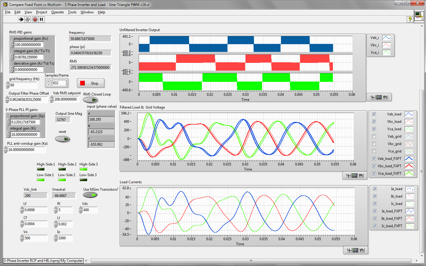
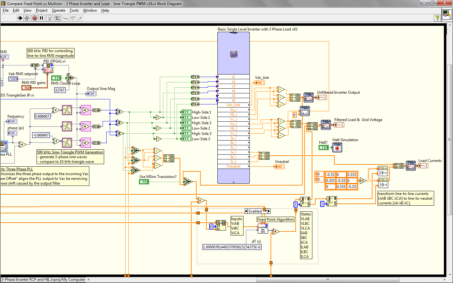
Compare Fixed Point vs Multisim - 3 Phase Inverter and Load - Sine-Triangle PWM v16.vi: Next compare the results from your fixed-point state-space model (that will be running in the FPGA of the cRIO-9082 system) against the Multisim results. Make sure the Multisim model and the LabVIEW front panel have the same component values. Also enter the correct Output Filter Phase Offset (pi) value to verify you control system is correctly doing the phase alignment to adjust for the output filter delay at the grid frequency.
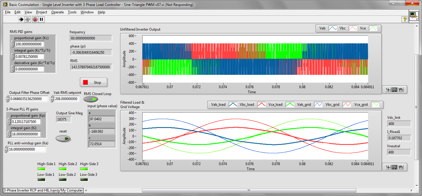
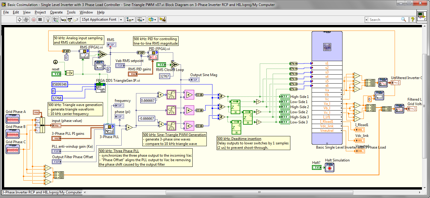
Basic Cosimulation - Single Level Inverter with 3 Phase Load Controller - Sine-Triangle PWM v07.vi: This is a basic co-simulation application to verify the control system logic with Multisim. This runs faster because it doesn't have the fixed-point state-space model in it. Use this to design and test new control algorithms on the desktop before compiling them to the FPGA for rapid control prototyping. Note that the same LabVIEW FPGA IP cores are linked in this desktop application and in the LabVIEW FPGA control system in that part of the project. If you change the algorithm in one place it is automatically updated in the other, and may require a recompile. For example, if you edit "IP Cores/FPGA DDS TriangleGen IP.vi" in your cosimulation application, it is automatically updated in the FPGA RCP loop. If you want to run an older version of the LV FPGA application, just like to the bitstream file rather than the VI and you won't be forced to recompile before running. However, your desktop co-simulation algorithms will no longer match the LV FPGA RCP algorithms.
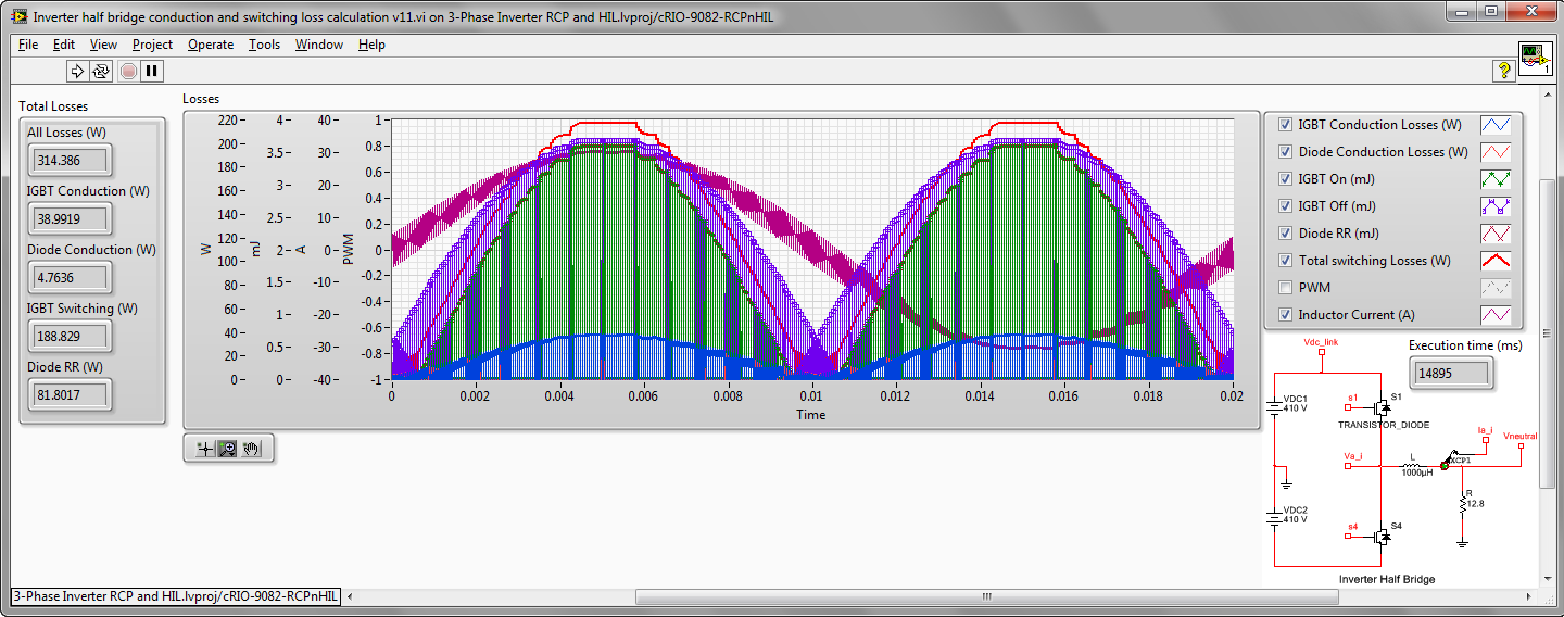
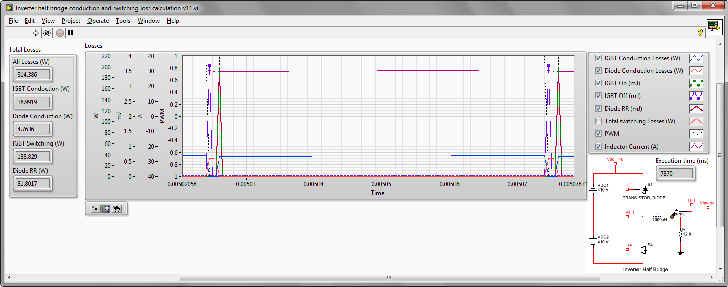
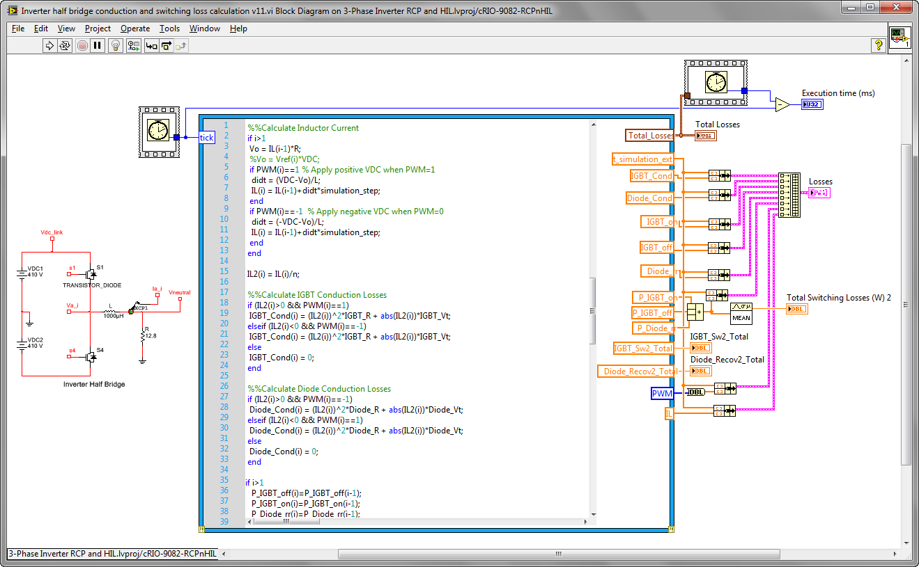
Inverter half bridge conduction and switching loss calculation v11.vi: This is a MathScript RT application that calculates switching and conduction losses for a inverter half-bridge stage (upper and lower switches) using the methodology described in this paper (MCBRYDE, JAMES. Inverter Efficiency Simulation and Measurement for Various Modern Switching Devices. Under the direction of Dr. Subhashish Bhattacharya). It is located under the CompactRIO Real-Time processor part of the project to show you Mathscript code executing in real-time. Be sure to pre-allocate your arrays to avoid memory allocation during execution of the simulation.
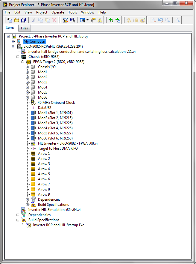
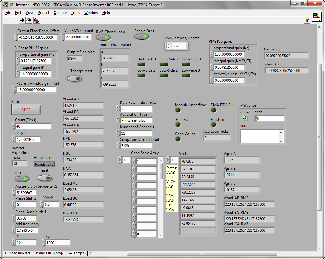
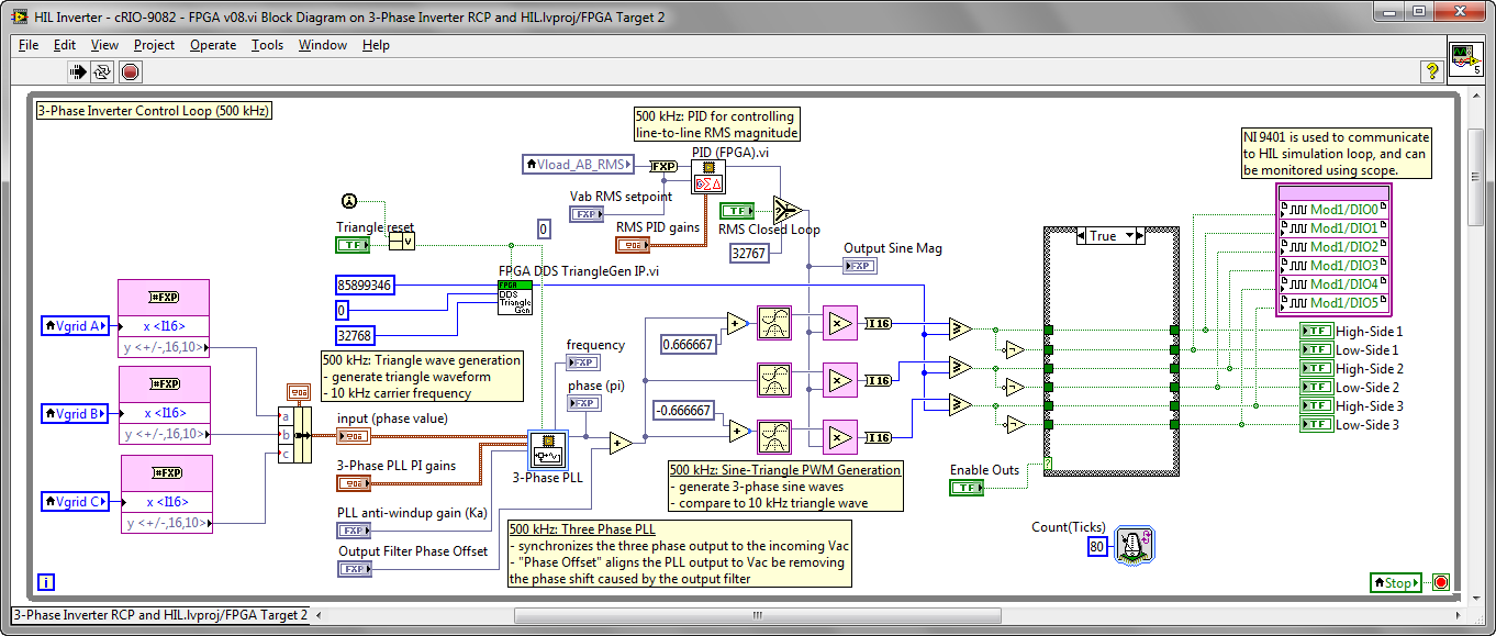
3-Phase Inverter RCP and HIL\HIL Inverter - cRIO-9082 - FPGA v08.vi: This is the LabVIEW FPGA application that contains both the control system code and the inverter HIL simulation code. If you want faster compile times, use a dedicated FPGA target for the HIL simulation so you only have to recompile when changing the control system code. This takes about 1.5 hours to compile on my relatively slow laptop. If you do all your development and code verification using the desktop co-simulation environment, you won't have to compile to FPGA very often.
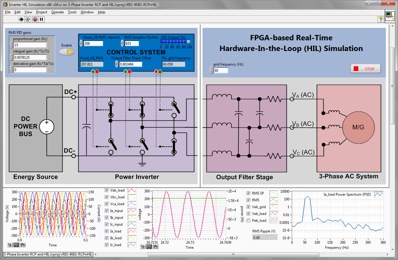
Inverter HIL Simulation x86 v04.vi: Shown below. This is the LabVIEW Real-Time application for rapid control prototyping and HIL. Use this to verify the correct behavior of the FPGA based control system executing against a real-time simulation of the inverter. This creates and environment for comprehensive design validation of your control system performance. For example, you can adjust control system tuning behavior and test the robustness of the control system to disturbances in grid frequency/phase/amplitude. Tools like NI Veristand and NI Teststand enable you to develop automated test suites. Any time you change or update your control algorithms, you can rigorously verify the correct behavior of the closed loop control system using test vectors capable of finding the "needle in the haystack" type bug that only occurs under a complex set of test conditions.
Parts List
A hardware bundle is now available with most of the parts needed to replicate this HIL system. Follow the link below for more information.
To replicate this reference design, order the following parts.
| Quantity |
Part Number: Description |
Purpose/Description |
|---|---|---|
| 1 | 781787-02: CRIO-9082 RT, 1.33 GHz Dual-Core Controller and LX150 FPGA with Real-Time | High performance CompactRIO with 180 DSP multiplier cores (minimum of 93 required). If your main goal is HIL simulation rather than RCP, the
PXIe FlexRIO PXIe-7966R is recommended. |
| 1 | 779351-01: NI 9401 8 Ch, 5 V/TTL High-Speed Bidirectional Digital I/O Module | Slot 1: High speed digital I/O module used to monitor or externally control the PWM gate drive signals for the six IGBT switches. If used for monitoring only, this is optional. |
| 1 | 781922-01: NI 9924, Front-mount 25-pin D-SUB to screw terminals accessory | Screw terminal accessory for NI 9401 module. Alternately, you could also use a 25-pin DSUB cable (192568-01: 25-pin DSUB, shielded female to male, 1m). |
| 4 |
779012-01: NI 9263, 4-Channel, 100 kS/s, 16-bit, ±10 V, Analog Output Module |
Slots 5-8: Used to monitor the AB load voltage and line-to-line filter and load currents. Note that the currents are not the phase currents in conventional line-to-nuetral format. This is optional. |
| 4 | 190656-01: Cable, 10 Pos Combicon to Pigtail, 1 Meter | DSUB cable used to wire analog output signals from the NI 9263 modules to the control system under test, such as the NI Single-Board RIO General Purpose Inverter Controller (NI 9683) |
| 1 | 782590-01: Eval Kit, NI sbRIO General Purpose Inverter Controller (GPIC) | Deployment-ready commercial embedded system designed to meet the cost, I/O, and performance needs of most high-volume commercial power electronics control applications, including DC-to-AC, AC-to-DC, DC-to-DC, and AC-to-AC converters for smart-grid flexible AC transmission systems (FACTS), renewable energy generation, energy storage, and variable speed drive applications. (http://www.ni.com/gpic) |
| 1 | Design Files: NI GPIC Screw Terminal Breakout Mating PCB Board Template with SKiiP 3 Connector | Interface board for the NI sbRIO GPIC that includes screw terminal connectors for all 134 I/O channels on the NI sbRIO GPIC. Order from your PCB fabrication house of choice. Alternately you can order from Sunstone Circuits using quote number FQR287178 (use at your own risk- this is example PCB only.) Connect the NI GPIC analog inputs to the multicore CompactRIO analog outputs (slots 5-8). Connect 8 channels of the NI GPIC LVTTL digital outputs to the multicore CompactRIO digital inputs (slot 1). |
Below is a photo of the NI Single-Board RIO HIL setup in the table above. (However, a different version of the mating PCB is used.) As you can see, all 16 analog inputs on the NI sbRIO GPIC are connected to analog outputs of the Multicore CompactRIO HIL system. The HIL voltage outputs are scaled to match the signal scaling of the LEM current and voltage sensors of the physical inverter, so the sbRIO GPIC system "thinks" it's connected to a physical inverter. Here is a template for the inverter control code that runs on the sbRIO GPIC (tutorial and download). The gate command signals are sent both to that half-bridge digital outputs and LVTTL digital lines that are connected to the NI 9401 module in the Multicore CompactRIO HIL system.
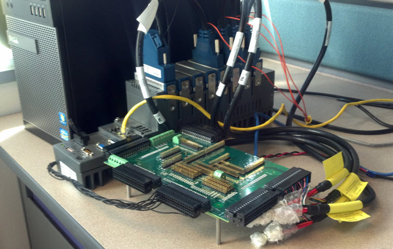
Note: Optionally you can add two NI 9239 modules to your Multicore CompactRIO HIL system and use them for electrical power measurements (harmonics, flicker, THD, etc.) on both HIL simulated and physical inverter testing systems.
Development Suggestions and Advice
A number of people have asked about what hardware is recommended for real-time simulation of power electronics (inverters, motors, generators, rectifiers, etc.). Here is some information on that, and some other recommendations and tips.
Screenshots
LabVIEW Project:
IP Core Testbench Applications:
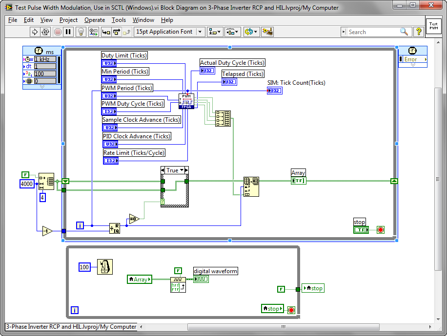
Test Pulse Width Modulation, Use in SCTL (Windows).vi
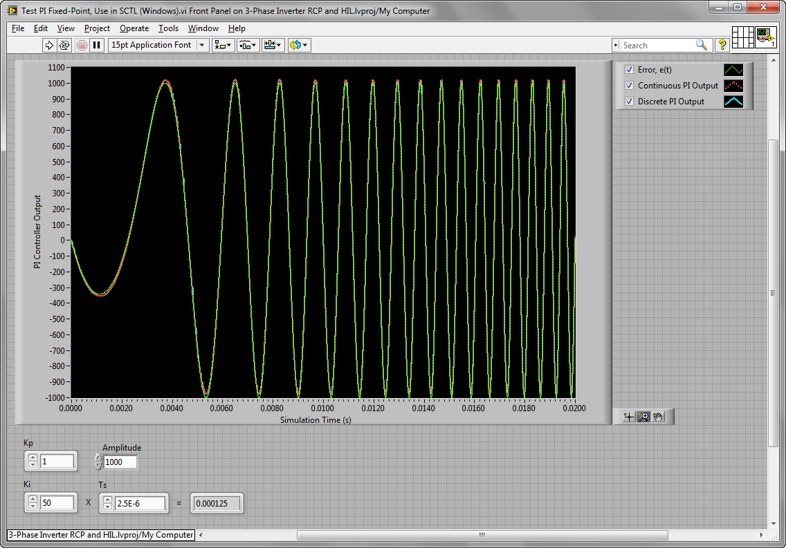
Test PI Fixed-Point, Use in SCTL (Windows).vi
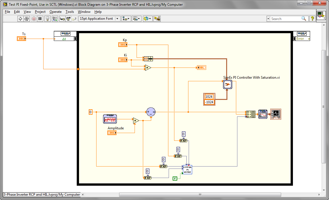
Block diagram of PI control algorithm that executes in a single clock tick of the FPGA:
.png)
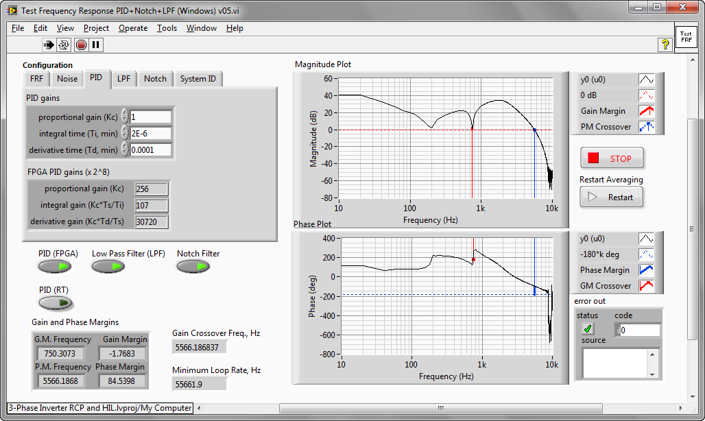
Test Frequency Response PID+Notch+LPF (Windows) v05.vi
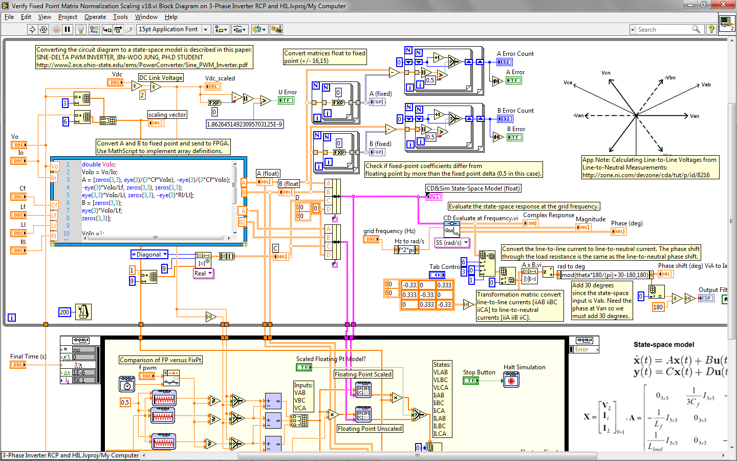
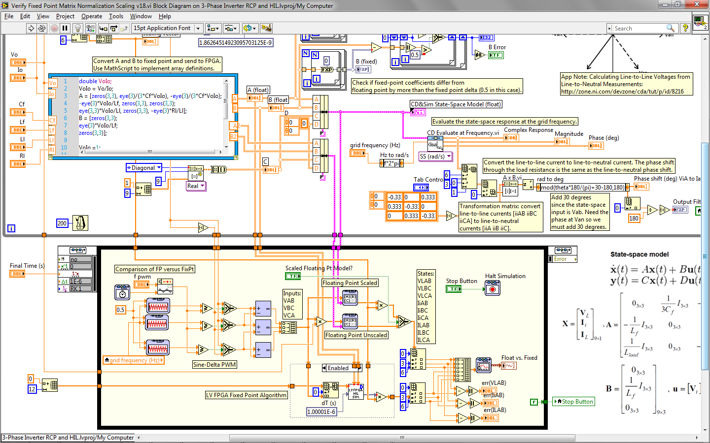
Verify Fixed Point Matrix Normalization Scaling v18.vi:
Compare Fixed Point vs Multisim - 3 Phase Inverter and Load - Sine-Triangle PWM v16.vi:
Basic Cosimulation - Single Level Inverter with 3 Phase Load Controller - Sine-Triangle PWM v07.vi:
Inverter half bridge conduction and switching loss calculation v11.vi:
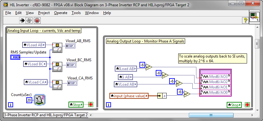
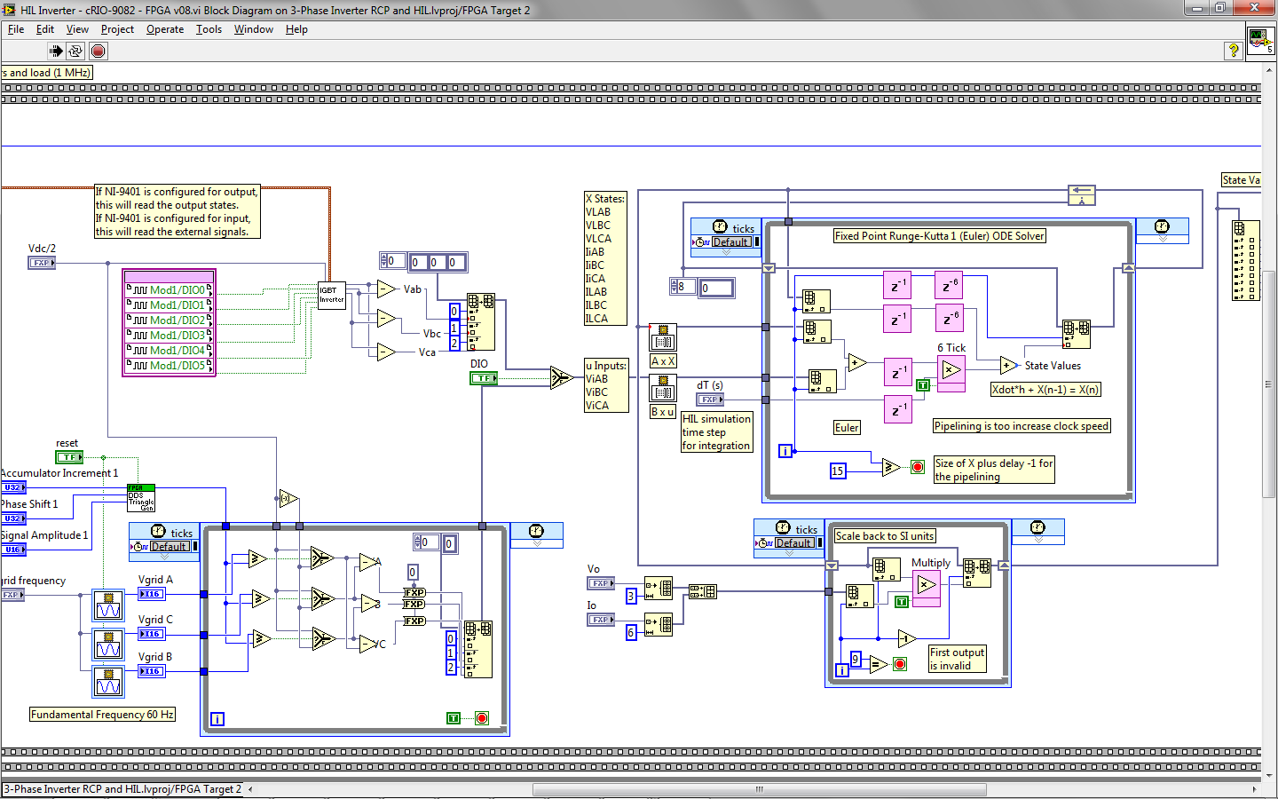
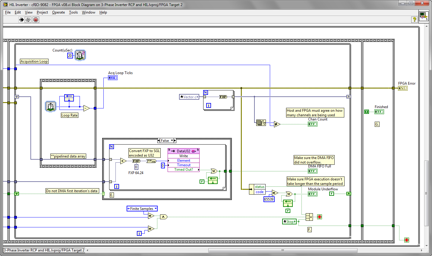
3-Phase Inverter RCP and HIL\HIL Inverter - cRIO-9082 - FPGA v08.vi:

Inverter HIL Simulation x86 v04.vi:
The software installers and code for this RCP and HIL system are available for download as part of the power electronics design guide.
01-04-2012 12:13 PM
A number of people have asked about what hardware is recommended for real-time simulation of power electronics (inverters, motors, generators, rectifiers, etc.). Here is some information on that, and some other recommendations and tips.
02-04-2012 02:47 PM
Hi
Where I Found this file "MultisimEMICtrl.dll"
and how solve this Errors:
An error occurred in compiling this VI.
Error -2367 occurred at External Model
Possible reason(s):
Control Design and Simulation: The shared library corresponding to the external model returned an error.
Unable to load library.
03-19-2012 05:08 PM
Hi Sammak,
Most likely you don't have the NI Multisim Co-Simulation Interface installed. This is an option when you install Multisim- be sure to install NI LabVIEW 2011 SP1 and the NI Control Design & Simulation Module first, and then install the NI Multisim Full, PowerPro or the NI Multisim Education Edition. See this tutorial for screenshots of the installers, where you can see the option to install Co-Simulation.
Note: Co-Simulation is not supported with NI Multisim Base.
The software installer download links are here.
10-01-2014 06:17 AM
Hello,
Can somebody explain me how the memory blocks are being used in the real time simulation, plis?
In the block diagram of the real time simulation, there is a matrix multiplication (A multiply by vector X), I know the vector X is calculated from the RK1 method. However, I am really having difficulties understanding how the values of the matrix A are assigned to the memory blocks, i.e., to "A row 1" (memory block) and so on. For example, if I want to change the values of R, C and L in the plant, how can I assign these values to the memory blocks to finally multiply the matrix A by the vector X. Am I misunderstanding something in here?
Thanks for your help!
10-04-2014 11:07 AM
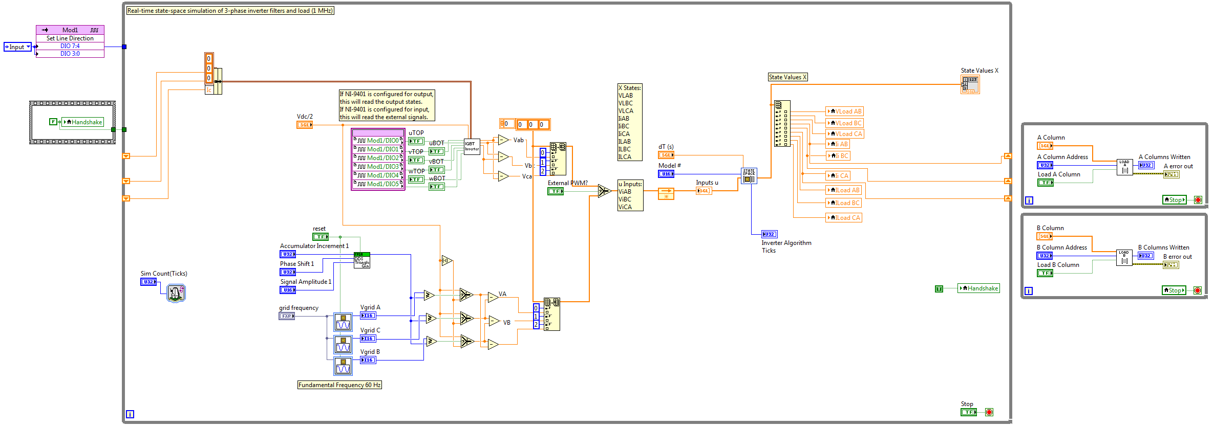
I'd recommend you move to the new graphical floating point version of the FPGA state-space simulator. In floating point, it's a "universal simulator" meaning you can simulate any state-space model without needing to (change the data types and) recompile the FPGA. Also, it includes loops used to write the A and B matrix coefficients in run-time. In the old fixed point solver, I believe you had to load them into FPGA RAM initialization values before the compile. The loops to write the A and B matrices (one column at a time) are on the right side of the screenshot below.
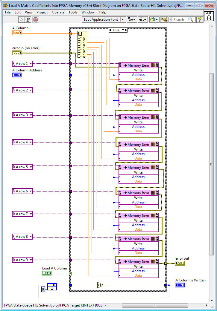
Here's the contents of the FPGA subVI that loads the matrix coefficients during run time. Since the state-space solver is a multi-channel implementation, the coefficients for N number of state-space models can be saved in FPGA RAM. A Column Address below refers to which Model # should be written. The Model # input to the solver (see above) determines which of the N models is simulated (taking inputs and calculating new outputs for a single timestep) at any given time.
For an example of calculating the matrix coefficients and loading a set (N number) of state-space model into the FPGA, see "../HIL Simulation\State-Space Solver\subVIs\[RT] cRIO-90xx Global Optimization Function.vi". Note that Mathscript Real-Time code is used to calculate the matrix coefficients based on the parameter values for capacitance, inductances and resistance. This particular state-space model (for an inverter 3-phase line reactor filter and reactive load) is detailed in this paper: SINE-DELTA PWM INVERTER, JIN-WOO JUNG, PH.D STUDENT
http://www2.ece.ohio-state.edu/ems/PowerConverter/Sine_PWM_Inverter.pdf
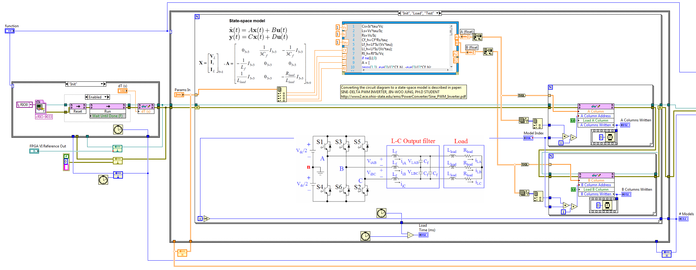
Note that the optimization example (part of which is shown above) is set up to identify the state-space model parameters based on measured time-domain and/or frequency domain (Bode plot) data. Alternately, you can use it to identify circuit parameters that match your design goal criteria.
Let us know if you have any follow up questions.
Best Regards,
BMAC
03-03-2015 07:04 AM
Hello, We have just received our NI Power Electronics RCP & HIL system in the recommended configuration.
It is not clear for me at this point if I have to order the Inverter Research Kit board from Bloomy as well or we can simulate the inverter control design on the SbRIO only and just interface the signals from the CompactRIO to the GPIC board? Could you please clarify what is the added functionality of the Bloomy board (inverter emulation maybe)?
Thank you.
03-09-2015 08:42 AM
Note: The state-space solver is now available as an example for the graphical floating point toolkit, which greatly simplifies development by eliminating the need to scale the state-space coefficients to appropriate fixed point word lengths. The floating point state-space solver is "universal" in the sense that it can simulate any state-space model (up to 9x9) without needing to recompile the FPGA or normallize/adjust coefficients-- making it more powerful and easier to use. A floating point transfer function solver is also available. Both the floating point state-space and floating point transfer function solvers are available as speed optimized (> 1 MHz) and resource optimized (> 100 kHz) versions. To learn more and download the toolkit and solvers, see whitepaper A and whitepaper B.
03-09-2015 10:28 AM
Congrats on receiving your NI Power Electronics RCP & HIL Bundle! There are three primary options for connectivity between the NI sbRIO GPIC control board and the cRIO-9082 HIL simulator:
1. Use the open source mini-scale back-to-back converter research kit (available from Bloomy in the United States, Schmid Elekronik in Europe, and SVTronics in other countries). To connect it, remove analog input jumpers from the inverter research board and connect the analog outputs from the cRIO-9082 to the simultaneous analog input connector for the NI GPIC control system. This is the recommended choice if you want to compare simulated versus physical measurements or perform system ID using a mini-scale plant connected to the mini-scale converter board (i.e. 3-phase induction or PMSM/BLDC motor or dynomometer from MotorSolver, line reactor filter, solar panel, battery, wind turbine, etc.) See below for details.
2. Use the open source SEMIKRON SKiiP3 interface board (available from SVTronics worldwide). This is the recommended choice if you want to connect to a full scale (50 to 125 kVA) 6-pack IGBT power converter such as the SKiiP3 from SEMIKRON or the SmartPower Stack from Methode Electronics. Note: The latest rev of this board has jumpers that enable you to disconnect the SKiiP3 sensor signals (phase currents, DC link voltage, temperature) from the GPIC analog inputs, so you will not need to disconnect the SKiiP3 connectors if you want to connect the interface board to your NI 9082 HIL simulator analog outputs. However, in most cases, you will still want to disconnect the full scale converter to disable its operation during HIL testing.
3. Use ribbon cable connectors to interface to the NI 9683 GPIC I/O board directly. In this case, you may wish to use a ribbon cable to screw terminal accessory to simplify wiring between the sbRIO GPIC control system and the cRIO-9082 power electronics HIL simulator.
Here are more details on option 1 and 2 above:
Note that electrical signals scale down linearly for the most part (transmission lines are an exception), so the mini-scale converter system is like an analog simulator for full scale power converters and power systems. R&D teams use multiple of these mini-scale converters, for example, to build microgrids with multiple asset types (i.e. gensets, wind/solar, storage converters) and power flowing between each of the converters. The software developed for the mini-scale converters is identical to that for a full scale converter (i.e. SKiiP3) with the exception of the scaling/gains and fault trip limits. All of these values are stored in FPGA RAM, so you don't even need to recompile the FPGA when you move back and forth between the mini-scale converter and the full scale.
You can do a fully digital HIL system where all of the signals are simulated. Optionally, utilizing a mini-scale physical inverter board like the kit from Bloomy or a full scale converter enables you to validate your digital simulation with real-world data.
See here for technical details on the mini-scale inverter board. Note that it is designed with jumpers (on the bottom side of the board) that enable you to disconnect the GPIC analog inputs from physical voltage/current/temperature sensors and connect them to analog outputs from your cRIO-9082 HIL system that represent simulated voltage/current/temperature values (from the NI 9263 analog output modules) . Also, the PWM gate command signals for the power converter are buffered out through the LVTTL lines on the GPIC for connection to the NI 9401 TTL digital input modules on your HIL system. If you want to disable the power inverters on the mini-scale converter board, just disconnect the +15 VDC supply (round barrel connector) from the inverter section of the board-- this disables the gate drivers for the physical inverter chips.
Thus, using the mini-scale converter board you can operate in two different modes:
1. "Completely digital sandbox." In this case all of the inputs and outputs to the NI GPIC control board are based on simulated signals from the NI cRIO-9082 HIL system. Therefore the analog input jumpers are removed and the analog outputs from the NI 9263 modules are connected to the mini-scale converter analog input connector. This is classical HIL simulation.
2. Simultaneous execution of HIL simulation and physical control. In this case, the physical signals are measured by the mini-scale converter board This is useful for system identification. The same control signals are sent both the cRIO-9082 HIL simulator and the physical power converter (mini-scale converter research board or full scale converter). Example code is available that demonstrates the use of a global optimizer to drive the difference between the measured and simulated signals to zero by automatically tuning the HIL simulation parameters. This is demonstrated for a buck-boost battery energy storage converter, a full bridge linear motor converter, and a magnetic levitation power converter. A real-time FPGA-based floating point simulation of the power converter and the physical plant model is included for each of these examples. The real-time power converter simulation model for the IGBT half bridge includes temperature modeling, as well as energy efficiency (download code or read white paper).
I hope this information is helpful. Please reply if anything is confusing or if you have any follow up questions.
