- Subscribe to RSS Feed
- Mark Topic as New
- Mark Topic as Read
- Float this Topic for Current User
- Bookmark
- Subscribe
- Mute
- Printer Friendly Page
LabVIEW FPGA algorithm development best practices
03-07-2012 11:50 AM
- Mark as New
- Bookmark
- Subscribe
- Mute
- Subscribe to RSS Feed
- Permalink
- Report to a Moderator
I'm working with a number of developers on porting their control algorithms from floating-point implementations on the desktop (within the LabVIEW Control Design & Simulation Loop) and moving them down to the FPGA for high speed execution (required if you want them to run above ~5 kHz). I thought it may be a good idea to share some information on best practices, tips and tricks and how-to knowledge for this LabVIEW FPGA "algorithm engineering" process.
In a nutshell, you must take advantage of the fact that you can run your LabVIEW FPGA code on the desktop.
0. STEP 0. Define your requirements and expectations for the algorithm you are developing. It's critical that you know what it is supposed to do before you start writing code. What will be considered a required feature? What is nice to have? How will you measure and validate the performance? How will you test the code? WRITE ONLY THE REQUIRED PART FIRST. GET THAT WORKING. THEN ADD THE NICE TO HAVE. Increment the file numbers (v01, v02, etc.) so you can always go back to a working version after you break it when trying to add something new.
1. FIRST-- test it without co-simulation. This is "functional simulation." Just copy your FPGA code from the block diagram of your FPGA VI to a blank VI on the desktop (create a new VI under My Computer) and test the functionality. Does it work the way you expect? Put it in a loop, feed in some signals and check. You can do something as simple as making some sliders on the front panel to make your own test signal manually, to feeding in white noise and dropping down a frequency response function (FRF) analysis VI to look at the Bode plots. Scaling is the most common problem you will run into. Always use functional simulation to test your scaling.
2. SECOND-- test it with co-simulation. This is "dynamic simulation" which captures the full closed loop dynamics.
3. FINALLY-- compile it to the FPGA target. You already know it will work, so grab a bite to eat and a coffee while it compiles and relax. You are following best practices so you can have confidence.
RESIST THE TEMPATION TO COMPILE YOUR FPGA CODE BEFORE FULLY TESTING IT. YOU SHOULD CONSIDER IT "CHEATING" TO DO SO. YOU JUST MIGHT GET AWAY WITH IT BUT YOU PROBABLY STILL DON'T ACTUALLY UNDERSTAND THE CODE SO IT WILL BITE YOU IN THE LONG RUN.
Trust me. On average, your development time will be faster, more productive, and the results more robust and reliable.
Adopt a formal approach to development- define your requirements, write the code to match the requirements, verify that it matches your requirements, THEN compile to the FPGA. Most people are doing this is reverse order, trying to save time! It doesn't save time. It's backwards.
This slide deck from 2006 has a summary of recommended best practices for developing LabVIEW FPGA algorithms. I produced the PDF with slide notes so you have more detailed explainations for each concept.
03-07-2012 12:04 PM
- Mark as New
- Bookmark
- Subscribe
- Mute
- Subscribe to RSS Feed
- Permalink
- Report to a Moderator
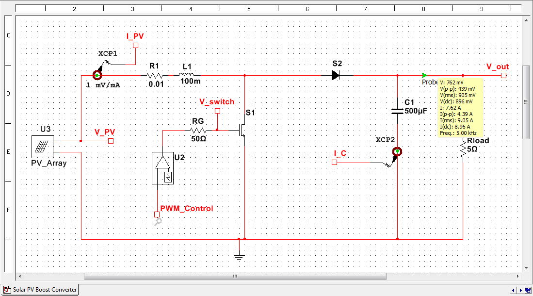
The new solar PV boost converter maximum power point tracking example in the design guide is a good example of how to move from a floating point to a fixed point FPGA implentation of a control algorithm (download link).
Here is the solar photovoltaic array boost converter Multsim schematic.
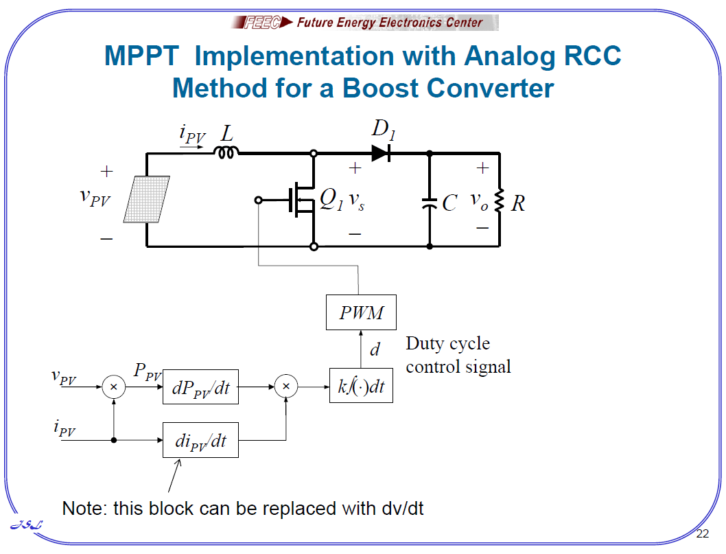
I decided to implement this algorithm that was highly recommended by one of the presenters at the APEC conference a few weeks ago (for it's simpliciity, millisecond speed and "mysterious ability" to find it's way out of local minima-- which can be caused by shading).
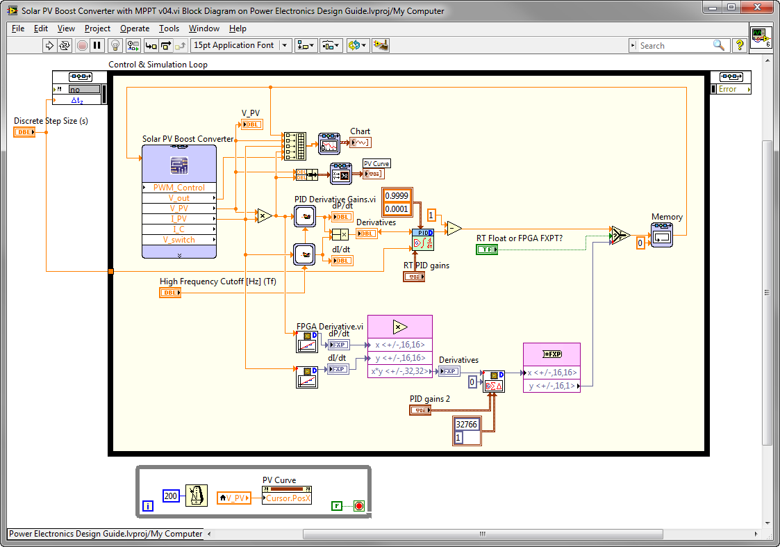
It was very easy to implement it in floating point within the LabVIEW Control Design & Simulation loop, co-simulating with the PV array and boost converter circuit in Multisim, as you can see.
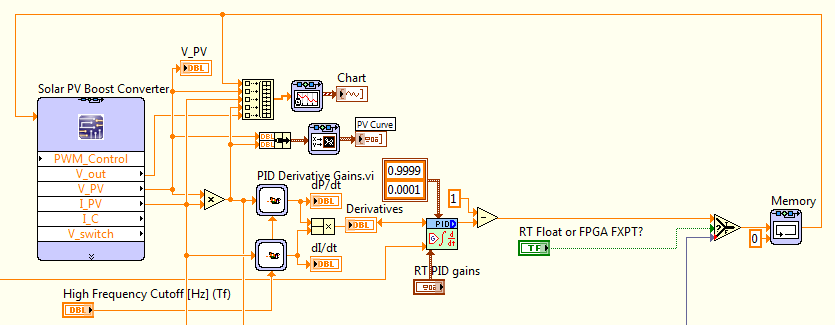
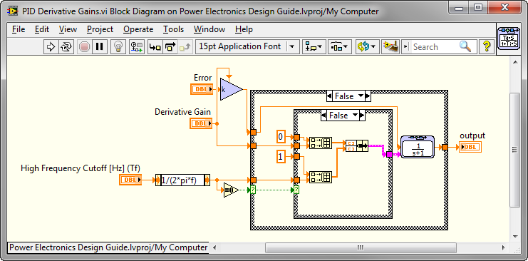
I chose to use the PID Derivative Gains function because it has the High Frequency Cutoff [Hz] feature. Use a pure derivative is never a good idea in an actual control loop, because the derivative of noise is off the charts. This is simply implemented as a transfer function with the appropriate poles and zeros as shown below. This is the block diagram of the LabVIEW CD&Sim subsystem. (Subsytems execute differently than subVIs- see the CD&Sim help for details.)
After spending some time tuning the High Frequency Cutoff [Hz] and PID gains, I was happy to see it working! It definitely needs more refinement, tuning, etc. but it seems like the basic algorithm is basically working. There is definitely more work to do-- it can get stuck at zero power for example, and it seems to sit below the actual MPPT point. But, I figured refinements could come later. The XY chart works really well for visuallizing the PV curve and I use the cursor to indicate the current tracking point.

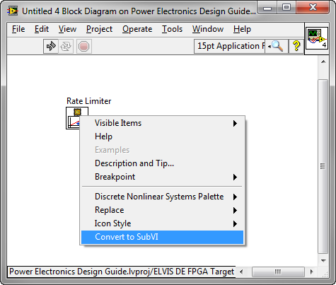
I thought that was a good start so I moved on to creating the FPGA version of the algorithm. First, I set out to make a fixed point FPGA derivative function. The first thing I thought of was the rate-limiter function, since that must have a derivative calculation built in. I went to my FPGA target in the LabVIEW project, right-clicked to creat a new VI, and dropped down the Rate Limiter.VI from the palette (FPGA Math & Analysis>Control>Discrete Nonlinear Systems). NI believes in the concept of "LabVIEW to the pin," meaning that there shouldn't be any black boxes that you can't dive into and hack the code. To access the underlying LabVIEW G code, I right-clicked and selected Convert to SubVI as shown.
Then I could access the block diagram, which is shown below.
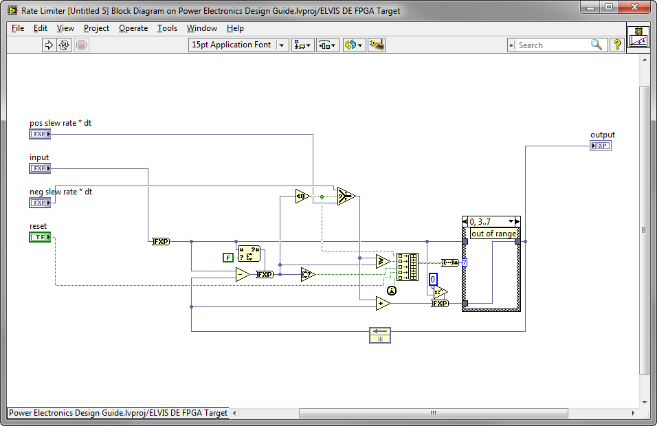
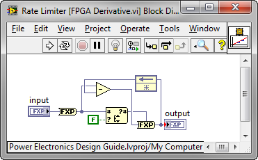
I saved it with a new name into my IP Core library, and started hacking. The only part I want is the derivate calculation. I also edited the icon a bit.
Now I implemented the whole algorithm (derivatives on power and current multiplying and feeding into a PID algorithm which acts as my integrator). I kept the floating point version in the same co-simulation loop so I can easily switched between and compare the two. They both are always running, but only one of them actually controls the solar PV boost converter circuit. I use the LabVIEW FPGA PID algorithm.
Note: Due to a known issue in this release, there are a number of LabVIEW FPGA VIs from the pallette that won't work properly within the CD&Sim loop for co-simulation unless you first Convert to SubVI and save as shown above. So in my case, I actually used the version of the PID VI that I had saved in my IP Library folder, since I had already done that conversion. As an example, the RMS function is another example of a function that must be converted before using in co-simulation. It's typically the ones that have a wizard type interface, which have the problem. These are called "Instance VIs". Fortunately, the workaround isn't too bad.
Here it is! After a few minutes of tuning the PID, the FPGA version of the MPPT was off and running! I smiled because my laptop was just about to run out of batteries and the airplane has no charging. 
And I was happy to see the FPGA version performing about the same as the floating point version in trying to track the MPPT, just as my laptop ran out of batteries and put itself to sleep. Not bad for a couple hours of algorithm engineering on an airplane. This is a lot more fun that watching a B movie on the little screen away.

