- Subscribe to RSS Feed
- Mark Topic as New
- Mark Topic as Read
- Float this Topic for Current User
- Bookmark
- Subscribe
- Mute
- Printer Friendly Page
Help needed with three phase pll to measure 60 HZ frequency
10-27-2013 12:52 PM
- Mark as New
- Bookmark
- Subscribe
- Mute
- Subscribe to RSS Feed
- Permalink
- Report to a Moderator
Hello everyone,
My application is to measure the three phase frequency at two ends of the switch (one is the grid side and the other one is the micro grid side). Currently, I am using the following hardware to measure the frequency.
1. sbrio 9642
2. I am using the built in NI 9205 analog input to measure the six line to neutral values. I have a potential transformer to step down the three phase voltages to one hundreth of the actual value. It comes out to be around + or - 2.9 Volts peak entering the 9205
a. I have seven analog inputs initiated, six for the line to neutral voltage values and one to read the status of the switch.
b. The fixed point type is <+ - 26, 5>. I enter this infoprmation in the three phase pll block available in the FPGA vis
3. I am using Labview FPGA project to perform this application.
4. The proportional gain is 0.120117, and integral gain is 10, and the antiwindup gain is 10. dt for the pll is 5.55*10^(-5).
I have also attached the picture of the RT side VI. I also have an anlog output enables in the FPGA VI for testing purposes. It basically generates a sinusoidal waveform in the analog outputs. But, this can be ignored because most of the time i use the actual waveforms from the three phase PT instead of the analog output.
When I connect my PT's to my analog input, I am able to see the three phase voltages in my RT vi. When I turn on and off the swicth I can see the voltages going to zero. This means that the analog input is entering the sbrio 9642 and I am able to see it in the RT side. But, what I am having trouble is the frequency and the phase values. The frequency just oscillates between 35 Hz and 85 HZ.
I took the values for my three phase pll from the power electronics design guide pdf file in page number 139. I have tested this vi with different fixed point types and also you can see that in one pll i use the phase values and in the other pll i use the line values. But, I am not having good results with this vi.
I have attached the pictures of my code with this discussion.
I would like this pll to get the 60 HZ frequency and be able to detect any deviation in the input frequency. I have been working on this for the past three weeks, any help would be appreciated to move this forward.
Thank you.
- Kumar
10-29-2013 12:25 PM
- Mark as New
- Bookmark
- Subscribe
- Mute
- Subscribe to RSS Feed
- Permalink
- Report to a Moderator
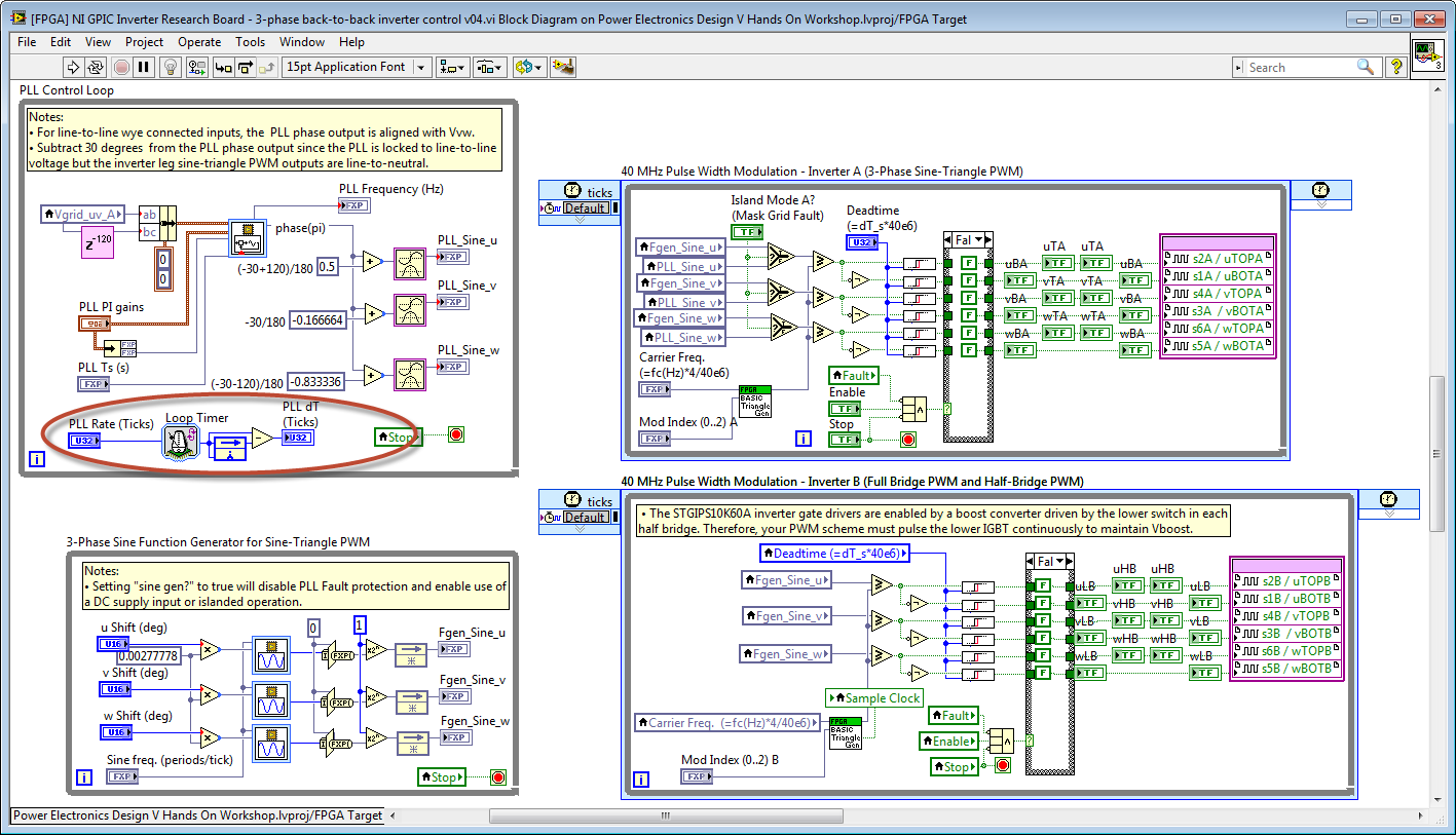
Most likely the problem is caused by the signals being connected in the incorrect phase sequence. The 3-Phase PLL on the LabVIEW FPGA palette requires a positive phase sequence. However, for line-to-line wye connected inputs, the PLL phase output is aligned with Vvw.
See the FPGA application below as a reference.
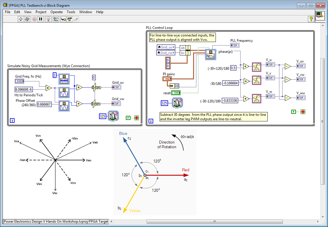
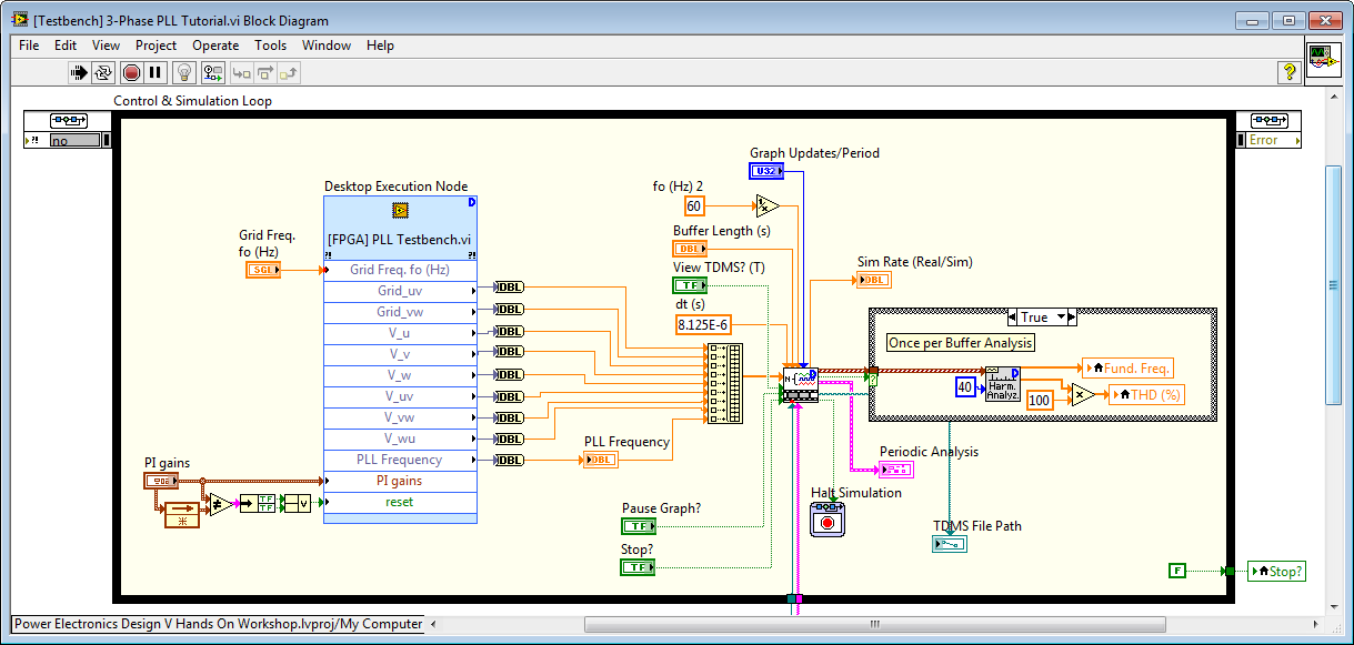
Using the new LabVIEW FPGA Desktop Execution Node (DEN), we can easily test FPGA applications like the one above while benefiting from the full debugging capabilities of LabVIEW for Windows (breakpoints, probes, highlight execution, etc.). The front panel and block diagram are shown below.
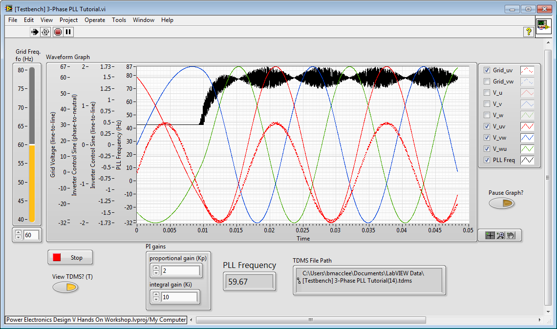
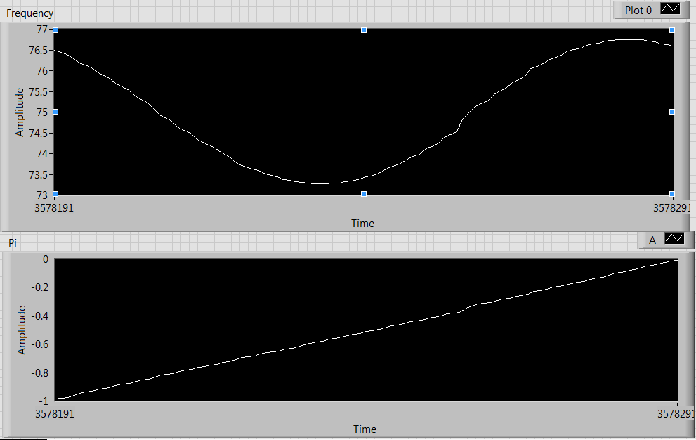
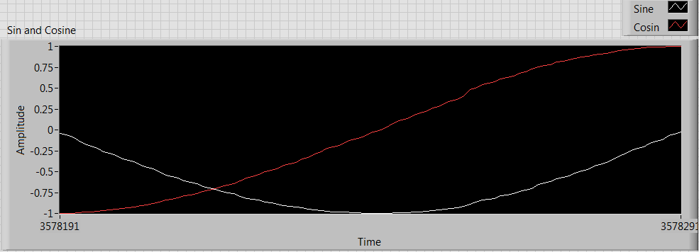
Notice how PLL Frequency is initially 30 Hz and takes a half cycle to begin tracking the noisy simulated grid waveforms. You can see the frequency of PLL in the indicator labeled PLL Frequency. Due to the noisy nature of the 3-phase grid waveforms and the aggressive tuning of the PLL proportional-integral (PI) control system, the PLL Frequency oscillates around the correct grid frequency.
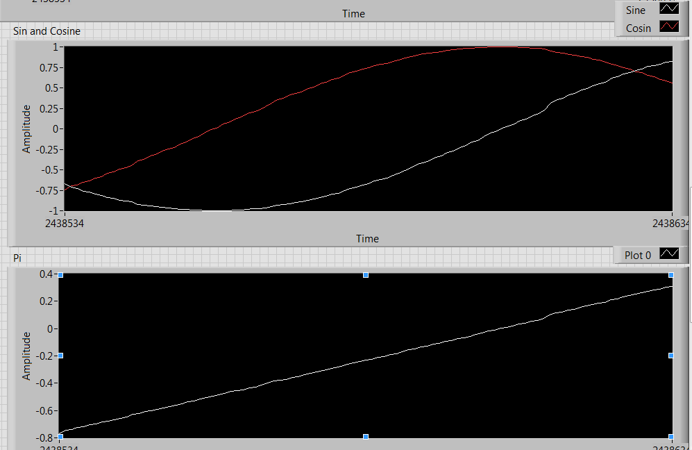
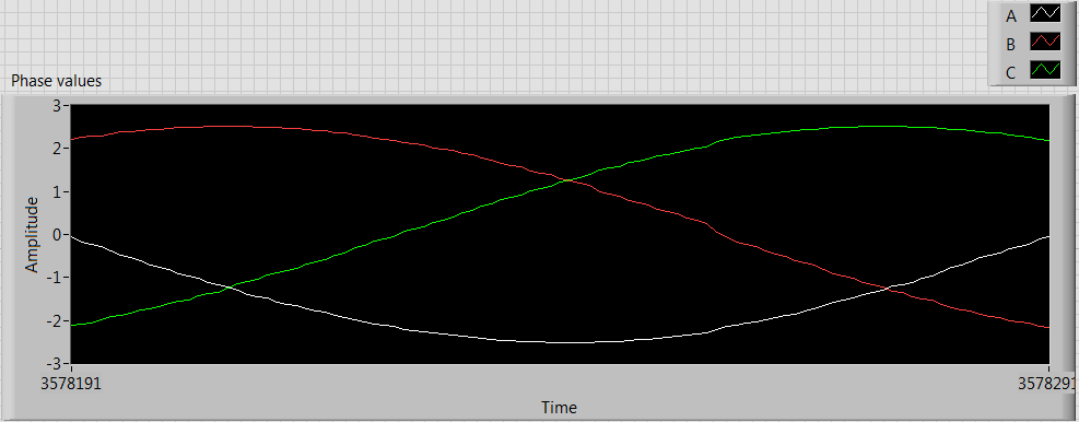
Note that the red V_uv waveform is phase aligned with the red Grid_uv waveform. Meanwhile, the blue V_vw and green V_wu waveforms are shifted by +240/-120 degrees and +120 degrees respectively.
Suggested exercises:
1. Vary the frequency of the simulated grid by changing the slider value labeled Grid Freq.fo (Hz) . Observe the fast tracking response of the PLL and generated three phase signals.
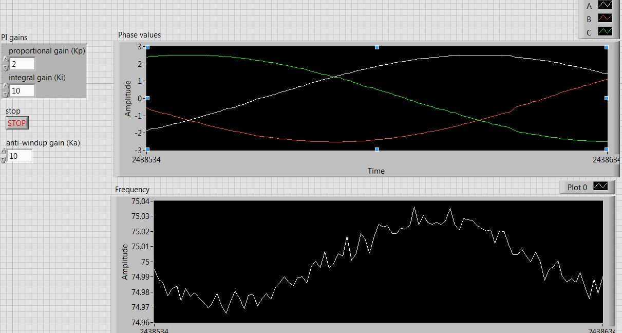
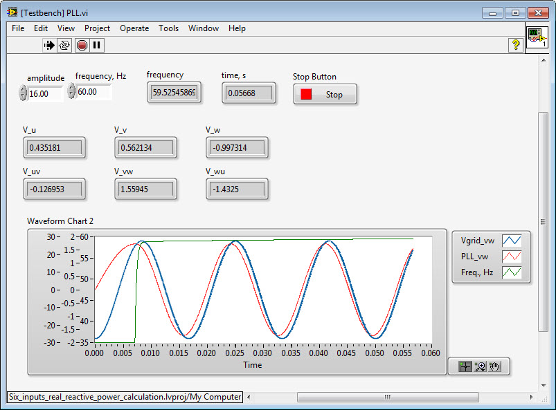
Below you can see that the PLL does a good job in quickly tracking a change in the grid frequency from 60 to 75 Hz, then to 45 Hz, then back to 60 Hz.
![]()
2. Changing the PI gains proportional gain (Kp) to a value of 0.2. How does reducing the proportional gain impact the magnitude of the PLL frequency oscillation? Now, vary the frequency of the simulated grid again and observe the tracking response. Why does reducing the PI controller gain result in less aggressive tracking?
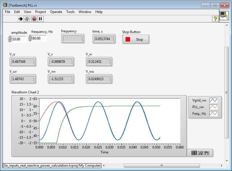
WIth a reduced proportional gain (P), below you can see that the PLL is much slower to track the change in grid frequency from 60 to 75 Hz, then to 45 Hz. At the end of the chart, it is still converging down towards the 45 Hz grid frequency. Note also that the reduced P gain results in less oscillation around the grid frequency, as we would expect. However, the disturbance rejection of the control system is reduced. The oscillation is due to the fact that we are injecting noise in the simulated grid signal.
![]()
For more information, please download the new NI Inverter Design V Step-by-Step Training Manual (PDF). This material is covered in module 2, exercise 1. The software for this training manual is not yet published online but is available on request- anyone interested should just email me at brian.maccleery@ni.com and I'll send you the code.
10-30-2013 08:55 PM
- Mark as New
- Bookmark
- Subscribe
- Mute
- Subscribe to RSS Feed
- Permalink
- Report to a Moderator
Hi Brian,
Thank you for your help. I have done some testing according to your response above. I have changed the pll program little bit and I have attached the changed pll pictures with this. I had two types of FPGA vi.
Case 1. In this one, the three phase line values a, b, and c are taken as input to the pll (PLL_FPGA_VI_1)
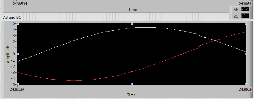
Case 2. For the second one, I obtain the V ab and V bc as shown (PLL_FPGA_VI_2)
Both of them gave similar results. I also played with phase sequence. I changed the phase sequence inputs to see if that makes any difference(in fact i tried all six combinations). It seems like the frequency either settles down at 75 HZ or oscillates around 75 HZ . I have attached the pictures with this. I am not sure why I am still not able to get the 60 HZ frequency.
Any help would be appreciated.
11-08-2013 02:26 PM
- Mark as New
- Bookmark
- Subscribe
- Mute
- Subscribe to RSS Feed
- Permalink
- Report to a Moderator
Hmm... It's hard to know without seeing your code. Looking at the waveforms, my guess is that the amplitude of the voltages is too low for the algorithm to work properly. Try multiplying the phase voltages by a gain so the inputs to the PLL function have an amplitude of at least 100. Keep in mind that the PI gains depend on the amplitude of the input signals, as explained in the online help for the 3-Phase PLL.
Some additional suggestions:
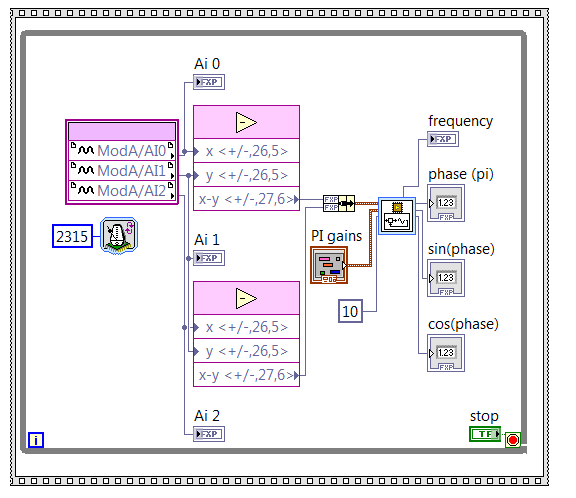
- Make sure the loop containing the PLL is actually executing at a rate that matches the dT (Sampling time, seconds) input to the PLL function. See below for an example. The rate is measured in FPGA clock ticks, where one tick represents 25 nanoseconds. Note also that a control is wired to the dT input of the PLL and the PLL anti-windup gain (ka) is wired to match the PI integral gain value.
- For the three-phase voltage inputs to the PLL, use "Bundle by Name" rather than bundle to make sure the signals are being connected to the correct terminals for each phase.
- Check the fixed point data type you are using to make sure it is compatible with the PLL.
- Try exercising your PLL loop with simulated I/O using the LabVIEW Desktop Execution Node (DEN) for LabVIEW 2013, as shown in the new inverter design V training manual (email for a link to the code).
11-08-2013 02:52 PM
- Mark as New
- Bookmark
- Subscribe
- Mute
- Subscribe to RSS Feed
- Permalink
- Report to a Moderator
Thank you for your reaponse. I will see if I can upload the code by today. I will also see if the gain can work.
- Kumar
12-06-2013 02:47 PM
- Mark as New
- Bookmark
- Subscribe
- Mute
- Subscribe to RSS Feed
- Permalink
- Report to a Moderator
Hi Brian,
I apologize for the delayed response. I have attached the files with this discussion.
Regards,
Kumaraguru Prabakar
12-10-2013 12:06 PM
- Mark as New
- Bookmark
- Subscribe
- Mute
- Subscribe to RSS Feed
- Permalink
- Report to a Moderator
I took a look at your code and found the problem:
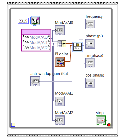
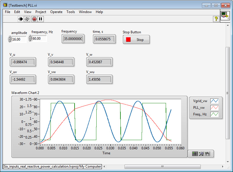
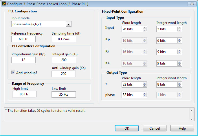
1. The loop rate setting for the LabVIEW FPGA while loop (2315 ticks/40e6 = 57.875 microseconds) does not match the internal configuration of the 3-phase PLL IP core (8.125 microseconds*40e6 = 325 ticks). This causes the behavior you are seeing in which the PLL is unable to find a lock within the Low limit and High limit range of frequencies in the IP core configuration panel (35 Hz to 85 Hz), as shown below in the testbench application I created.
Here is the PLL IP core configuration you have.
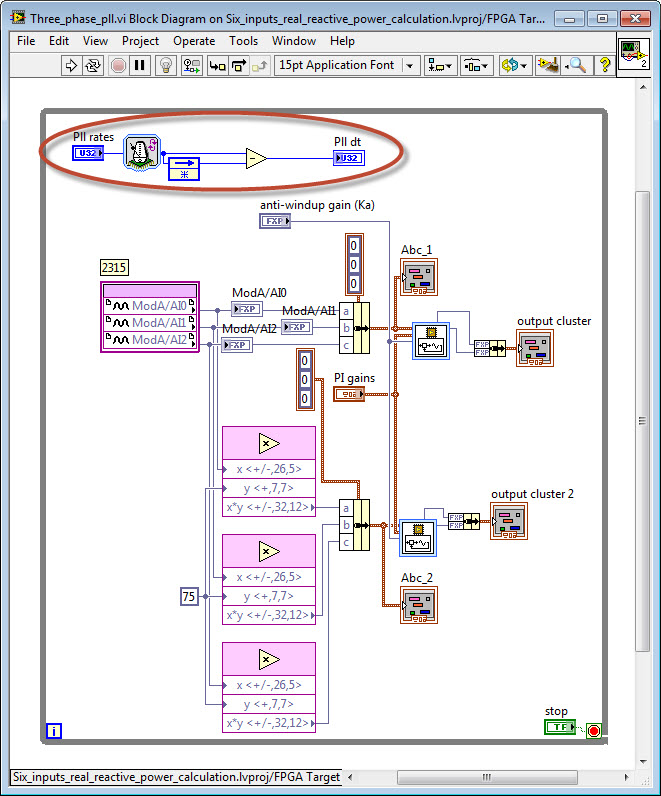
Here is where the loop rate is set in the FPGA loop containing the PLL. The loop rate must match the PLL configuration.
Note- You should also check that the analog inputs signals for the grid voltages are within the range of the analog inputs you are using (most likely +/- 10 V).
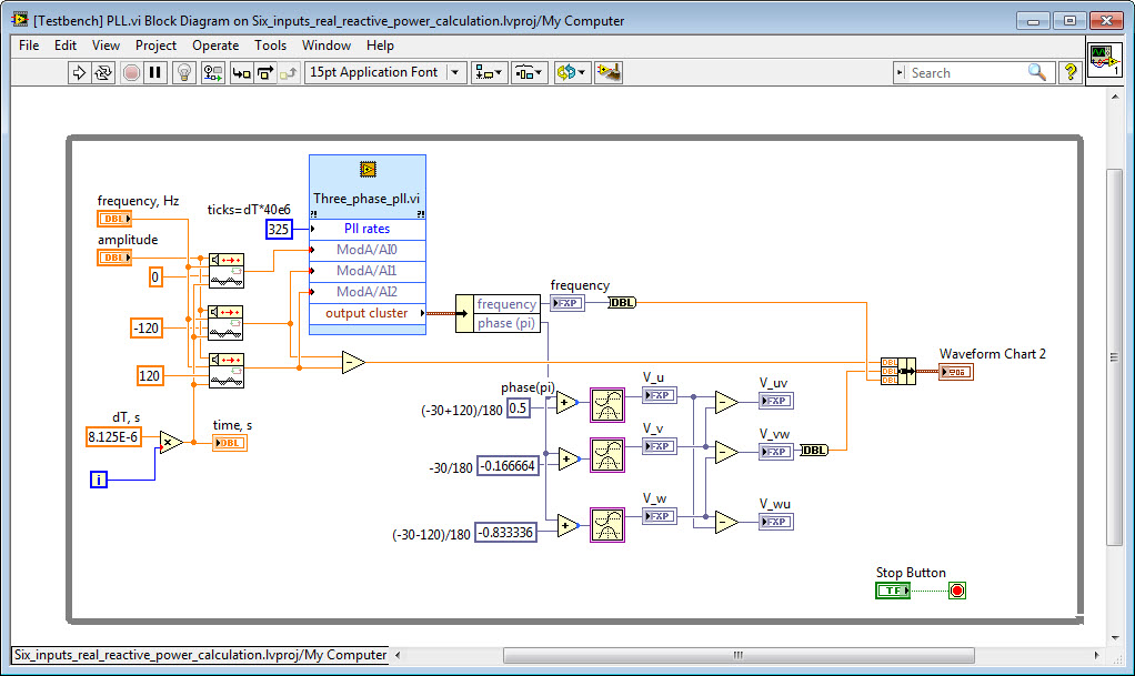
2. Next I changed the Pll rates value to 325 ticks, to match the 8.125 microsecond sampling time in the PLL configuration. Note that there is also an input terminal on the IP core that you can use to wire in the sampling time value. Now the PLL is working correctly.
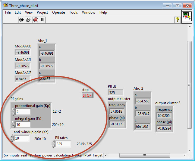
3. Finally, I adjusted the PLL gains to give a faster tracking response (what tuning you desire will depend on your application requirements. I also adjusted the analog input signal amplitude to +/- 10 V.
The FPGA front panel with updated PLL gains and loop rate is shown below.
You can download the updated project code with the Desktop Execution Node testbench application from here.
12-12-2013 12:40 PM
- Mark as New
- Bookmark
- Subscribe
- Mute
- Subscribe to RSS Feed
- Permalink
- Report to a Moderator
Hi Brian,
Thank you for your help with this issue. I tried the code with 325 ticks in the hardware and it was still not working. I changed the ticks back to 2315 and also changed the PLL time to around 57 micro seconds. I also updated my analog input update time to be as fast as possible around 250 kS/s. After making these changes the pll seems to work. It can track the frequency with an accuracy of 0.02 Hz. I am trying to tune the PLL to get even better accuracy.
This discussion forum is really helpful. I wish I could have posted my questions earlier.
Regards,
Kumara
02-16-2015 01:19 AM
- Mark as New
- Bookmark
- Subscribe
- Mute
- Subscribe to RSS Feed
- Permalink
- Report to a Moderator
Hi Bmac you seem to know a lot about PLL I have a similar problem, I have to use Pll to synchronize motor speed with a external clock frequenz. I don't really unterstand how to use this PLL VI to solve this problem, because I have square or Pulse wave signal(from the encoder) instead of sine wave and I have to come out with a PWM duty cycle (1khz frequenz) to drive the Motor. Is there any explanation about how to do that
Thx
08-04-2015 09:24 AM
- Mark as New
- Bookmark
- Subscribe
- Mute
- Subscribe to RSS Feed
- Permalink
- Report to a Moderator
Hello Everyone,
I am trying to measure the three phase frequency using PLL in FPGA. I read the discussion and I tried to do it, yesterday I was able to get the near to desired results but I think i need some advice.
I am using NI 9205. the frequency my application is based 50 Hz. Ticks set to 2315, and PLL time ti 57.8 us, I am using phase to phase measurement, Diff mode on +- 5 V.
The code I made is attached as attachment.
I would really thank for any suggestion.
Best regards
Arvin
