- Subscribe to RSS Feed
- Mark Topic as New
- Mark Topic as Read
- Float this Topic for Current User
- Bookmark
- Subscribe
- Mute
- Printer Friendly Page
LabVIEW Nugget of the week - Modbus Communication -
10-18-2012 04:20 AM
- Mark as New
- Bookmark
- Subscribe
- Mute
- Subscribe to RSS Feed
- Permalink
- Report to a Moderator
Dear LabVIEW Users,
Pada LabVIEW nugget minggu lalu kita sudah membahas bagaimana kita berkoneksi dengan PLC dengan contohnya yang menggunakan komunikasi via Modbus Protocol.
Sekarang mari kita lihat Modbus communication secara lebih menyeluruh.
Diambil dari http://www.ni.com/white-paper/7675/en
Introduction to Modbus :
Modbus is an application-layer protocol based on a master/slave or request/reply architecture. It was published by Modicon in 1979 and is primarily used in industrial applications.
The Modbus protocol follows a master/slave architecture where a master will request data from the slave. The master can also ask the slave to perform some action. The master initiates a process by sending a function code that represents the type of transaction to perform. The transaction performed by the Modbus protocol defines the process a controller uses to request access to another device, how it will respond to requests from other devices, and how errors will be detected and reported. The Modbus protocol establishes a common format for the layout and contents of message fields.
During communications on a Modbus network, the protocol determines how each controller will know its device address, recognize a message addressed to it, determine the kind of action to be taken, and extract any data or other information contained in the message.
Controllers communicate using a master/slave technique where only one device, the master, can initiate transactions or queries. The other devices, slaves, respond by supplying the requested data to the master or by taking the action requested in the query. Typical master devices include host processors and programming panels. Typical slaves include programmable controllers.
Using LabVIEW With Modbus
Modbus I/O Servers
The LabVIEW Datalogging and Supervisory Control (DSC) Module is the preferred way to have LabVIEW communicate with a Modbus device. The DSC module uses I/O Servers to handle all protocol between a master and slave. The I/O servers are used in the Shared Variable Engine(SVE) and allow the SVE to become both a Modbus master and slave. Modbus I/O servers are also included in the Real-Time module, so CompactRIOs can be used to communicate with other Modbus devices.
Modbus Master I/O Servers
The SVE can create Modbus Master I/O Servers to communicate with Modbus Slaves. A typical application is to have a computer running a LabVIEW application and the SVE be configured as a Modbus Master that then communicates with PLC that is configured as a Modbus Slave. Figure 12 shows how the I/O Servers and the SVE work together to allow LabVIEW access to Modbus coils and registers on a PLC.
Figure 12: LabVIEW and Modbus Network
The SVE uses the Modbus Master I/O server to communicate with the PLC using the Modbus Standard through either serial or Ethernet. The I/O Server handles low level communication protocol to provide faster development times. The SVE uses NI Publish-Subscribe Protocol (NI-PSP) to provide a PSP URL for each Modbus address. With a PSP URL, Shared Variables can be bound to the Modbus addresses by enabling aliasing. Once the Shared Variables are deployed to the SVE and communicating with Modbus addresses, then LabVIEW can easily read and write to the Shared Variables like in Figure 13.
Figure 13: Reading from Bound Shared Variables in LabVIEW
When the Shared Variable Engine binds the Shared Variables to Modbus addresses, reading and writing is simplified to directly reading from and writing to the Shared Variables on the block diagram. No extra code is required to initialize and close the connections. The bound Shared Variables can be published to the network, so any computer with LabVIEW can read from and write to the bound Shared Variables. For more specific steps on how to set up a Modbus I/O Server for the Shared Variable Engine see the Developer Zone: Connect to any PLC using Modbus.
Modbus Slave I/O Servers
The SVE can use Modbus Slave I/O Servers to allow for communication with Modbus Master devices. When designing an application that will run a LabVIEW application on a normal desktop computer, it is not typical to use Modbus Slave I/O Servers. A more common application is to have Real-Time targets such as the CompactRIO configured as slaves with Modbus Slave I/O Servers set up on a CompactRIO’s SVE, as seen in Figure 14.
Figure 14: Using Modbus Slave I/O Servers with a CompactRIO
CompactRIO targets can be deployed remotely in place of PLCs and allow for integration into Modbus applications. The SVE and Modbus I/O servers support must be installed on the CompactRIO Real-Time controller. LabVIEW Real-Time can be used to access the physical I/O from the C Series modules then write values to Shared Variables. The Shared Variables are then bound to Modbus addresses using NI-PSP and Modbus Slave I/O Servers. LabVIEW Real-Time interacts with Modbus addresses through Shared Variables in the same way as used in Figure 16. This way many CompactRIO targets can be deployed as Modbus Slaves that all communicate with a single Modbus master over serial or Ethernet.
NI Modbus Library
You can download free Modbus libraries for LabVIEW. It is recommended by NI to use Modbus I/O Servers provided in the LabVIEW Datalogging and Supervisory Control (DSC) Module or Real-Time Module. The modules provide easy to use Shared Variables for both Modbus TCP and serial. If you do decide to use the NI Modbus library a great point to start for your application is to look at the examples supplied with the libraries. There are examples for master and slaves for both the serial and TCP implementation of the Modbus protocol.
Contoh aplikasi menggunakan Modbus Serial : Komunikasi dengan Phasor Measurement Unit via Modbus Serial
Komunikasi dengan Flow Meter via Modbus Serial
Contoh2 disini menggunakan modbus library, bisa didownload di link pada LabVIEW nugget sebelumnya.
Semoga Bermanfaat
Regards,
Bian
- Tags:
- nuggets
09-18-2013 10:50 PM
- Mark as New
- Bookmark
- Subscribe
- Mute
- Subscribe to RSS Feed
- Permalink
- Report to a Moderator
Hey Bian,
I'm Nishant from Singapore.
I am trying to develop a communication system with Omron Power Meter (KM 50 E) which uses Modbus Protocol.
I do have an additional module MOXA 5130 device to convert it to RS485. Basically MOXA 5100 series devices are serial device servers that make it
easy to network-enable serial devices.
You you be able to give me a head start as to how do i start interfacing and programming using LabVIEW to retreive holding register values into LabVIEW?
Thanks for support.
Sincerely,
Nishant
04-14-2014 11:35 PM
- Mark as New
- Bookmark
- Subscribe
- Mute
- Subscribe to RSS Feed
- Permalink
- Report to a Moderator
hallo kak Bian,
boleh minta tolong ? ni sy baru belajar modbus RTU, kok agak susah ya. dulu sy udah bermain komunikasi serial tp pake rs232c buat mantau suhu pakek mikrokontroler atmega doang, pembacaannya dari ADC ny doang kn gampang tuh.
nah dsni sy mau pake modbus buat baca metering. sy lampirkan manual meteringnya berikut
http://circutor.com/docs/M98172501-03.pdf
untuk memory map :
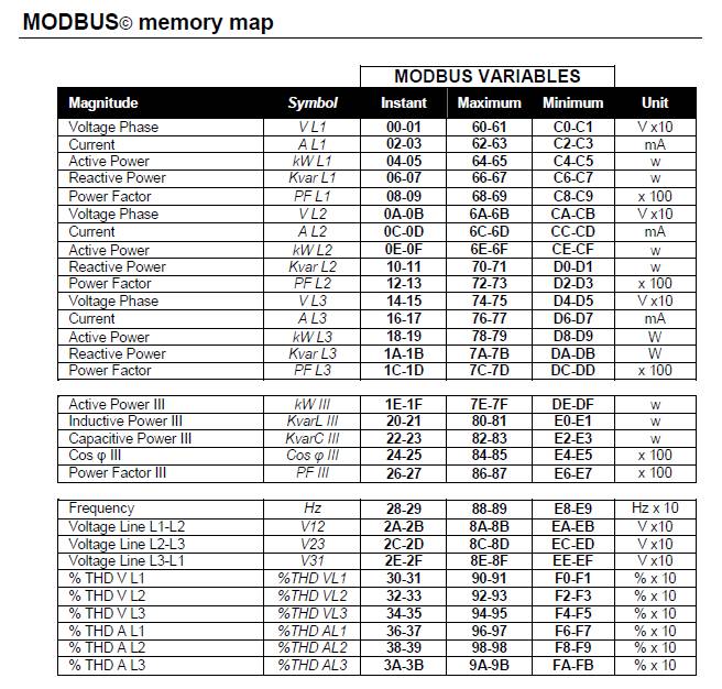
sy udah download ni visa, ni modbus library.
yang sy tanyakan:
1. brdsrkn apa yg sy ktahui ttg modbus dr manual metering tsb. modbus kan btuh request lalu alat tsb baru mau menjawab apa yang kita request kan ? nah yg kita request bentuknya hexadesimal kan, trus jwbnny juga hexadesimal. benar sprti itu ngga kak ?
2. kl benar, LabView bisa mengkonversikan ke bilangan desimal ? trus tgl kita edit jadi progress bar/meter/graphic maupun chart? soalnya dulu sy pke rs232c baca ADC datanya udah berubah jadi string, jadi mau di jadiin tampilan yg cantik gt gampang bgt. nah sy mau mempercantik tampilan dr modbus ini bs nggak ?
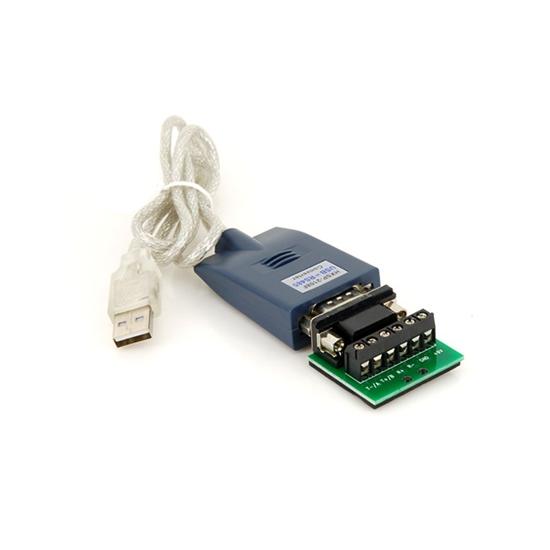
3. apakah converter yang hrus sy pakai sperti ini ?
udah tny itu dlu, mohon bantuannya kak, TERIMA KASIH
04-23-2014 10:34 AM
- Mark as New
- Bookmark
- Subscribe
- Mute
- Subscribe to RSS Feed
- Permalink
- Report to a Moderator
bian sudah tidak aktif lagi di labview, saya saja yang jawab ya:
1. brdsrkn apa yg sy ktahui ttg modbus dr manual metering tsb. modbus kan btuh request lalu alat tsb baru mau menjawab apa yang kita request kan ? nah yg kita request bentuknya hexadesimal kan, trus jwbnny juga hexadesimal. benar sprti itu ngga kak ?
--> ada dua cara, satu menggunakan NI Modbus Library, atau kedua, pakai sistem question-response, seusai dengan manual yang sudah sampeyan attach, halaman 34. Coba saya jelaskan yang question-response, berarti sampeyan akan menggunakan NI VISA Write (utk question) dan NI VISA Read (utk response).
Sementara untuk data yang ditulis dan dibaca, harus dalam bentuk hexadecimal (betul kata sampeyan). Gunakan String, dengan datanya dalam bentuk hexadecimal
2. kl benar, LabView bisa mengkonversikan ke bilangan desimal ? trus tgl kita edit jadi progress bar/meter/graphic maupun chart? soalnya dulu sy pke rs232c baca ADC datanya udah berubah jadi string, jadi mau di jadiin tampilan yg cantik gt gampang bgt. nah sy mau mempercantik tampilan dr modbus ini bs nggak ?
--> betul, bisa. Tentu saja dari response yang dibaca, kan bentuknya Hexadecimal, ya dikonversikan ke bentuk numeric.
Ini contoh di manual halaman 34:
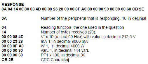
kita lihat yang:
00 00 08 4D
berikut ini konversi codenya dalam LabVIEW:
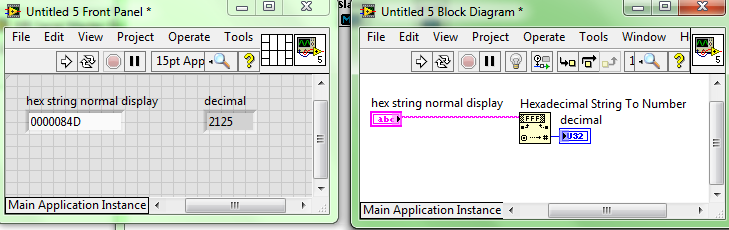
Output dari VISA Read pasti dalam bentuk String, jadi masuk ke fungsi seperti di atas, lalu dapat angka 2125, dan diubah saja menjadi 212.5
3. apakah converter yang hrus sy pakai sperti ini ?
--> bisa apa saja, tapi jalan atau tidak saya tidak menjamin ya, karena pernah ada pengalaman menggunakan converter buatan cina dan tidak jalan. Dicoba saja.
Certified TestStand Developer (CTD)
Using LabVIEW 8.5.1 (2008) to LabVIEW 2021
04-23-2014 08:30 PM
- Mark as New
- Bookmark
- Subscribe
- Mute
- Subscribe to RSS Feed
- Permalink
- Report to a Moderator
oh gt, beda yah modbus sm question response ? ada ebook ngga kak ? kl boleh minta dong materi2 ttg modbus & question - response.
mnrtmu enakan mana kak ? ada kelebihan dan kekurangan antara NI modbus library sm NI Visa ( Question - Response ) ?
OK, sy order converter itu dulu, nnti coba pake NI Visa kyny yg sudah familiar hehe. nnti tny lg ya kak kl ada mslh hehe,
Terima Kasih~
04-23-2014 09:24 PM
- Mark as New
- Bookmark
- Subscribe
- Mute
- Subscribe to RSS Feed
- Permalink
- Report to a Moderator
Kak sy udah coba kok respone nya aneh ya berubah2 ga jelas gt, ada yang salah ?
berikut programku
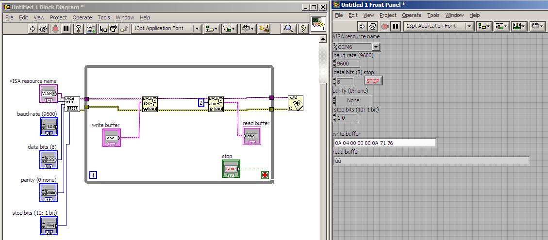
com port,baud rate,stop bit, data bit, parity udah sama semua
04-23-2014 10:07 PM
- Mark as New
- Bookmark
- Subscribe
- Mute
- Subscribe to RSS Feed
- Permalink
- Report to a Moderator
Coba cek string control dan indicator jika mode nya hexadecimal. Right click di control write buffer dan read buffer lalu pilih hex display.
04-23-2014 10:30 PM
- Mark as New
- Bookmark
- Subscribe
- Mute
- Subscribe to RSS Feed
- Permalink
- Report to a Moderator
mantab kak, ada peningkatan tp beda sm manualnya, hasilnya seperti ini
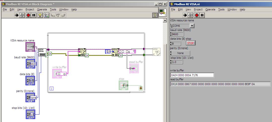
tapi kok beda ya sm manualnya, mksdny susunannya beda dkit. itu read indicator sy jadiin display hex jg jd bngung urutannya gmn hehe,
sedangkan di manual seperti ini
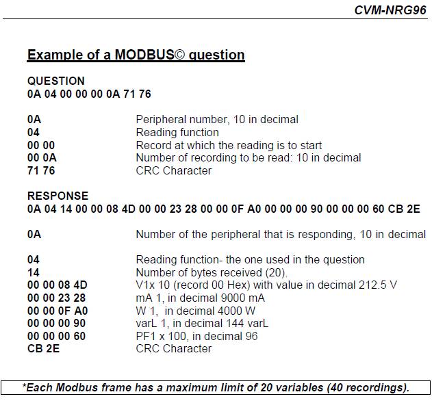
trus mw nny gmn kak caranya misahin misahinnya, tu kan hasil hex nya bnyk bgt sy mau pisah2in (mana yg Volt, Ampere, Watt, Var, PF) trus mw sy convert ke decimal
04-23-2014 10:59 PM
- Mark as New
- Bookmark
- Subscribe
- Mute
- Subscribe to RSS Feed
- Permalink
- Report to a Moderator
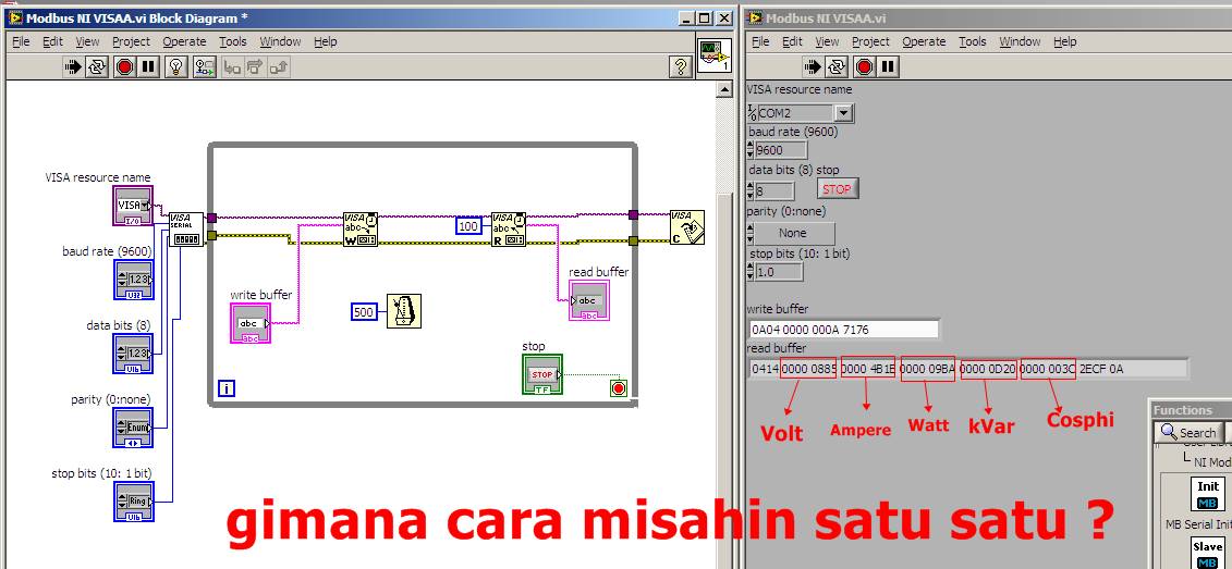
kak tuh hasilnya ? gmn caranya biar itu hasilnya misah satu satu kak ? mau sy convert ke decimal soalnya
04-24-2014 01:11 AM
- Mark as New
- Bookmark
- Subscribe
- Mute
- Subscribe to RSS Feed
- Permalink
- Report to a Moderator
Banyak cara, salah satunya dengan "String Subset" di string function pallete.
