From Friday, April 19th (11:00 PM CDT) through Saturday, April 20th (2:00 PM CDT), 2024, ni.com will undergo system upgrades that may result in temporary service interruption.
We appreciate your patience as we improve our online experience.
From Friday, April 19th (11:00 PM CDT) through Saturday, April 20th (2:00 PM CDT), 2024, ni.com will undergo system upgrades that may result in temporary service interruption.
We appreciate your patience as we improve our online experience.
02-05-2013 05:18 PM
Right now my team is making a tower with a hook system that goes up and down. As of now I have the tower programmed so I can control the speed the thing goes up using the axis 3 whiling holding a button, and the same for the thing to come down. Right now we have two limit switchs hooked up to the hook thing so when the object hits the limit switch the motor Should stop in that direction. How can I program a limit switch to do that? I don't know how to program a limit switch at all. Below I have a picture of my code for the motor going down without a switch, so how do I make that work until I hit the bottom limit switch thanks a ton. Visuals are awesome. Thanks
02-06-2013 08:29 AM
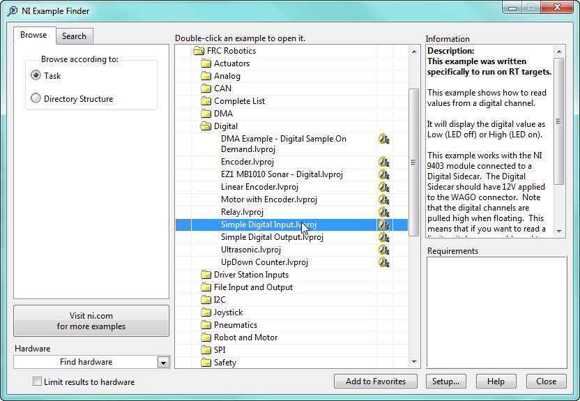
Review the "Simple Digital Input" example in the NI Example Finder found in LabVIEW. Wire up a limit switch to run with the example and see how it works.
You will need to put a WPI_DigitalInputGetValue.vi in both your "Up" case and your "Down" case. Use the Boolean "Value" output to set the motor speed to 0 when the limit switch is closed. Over riding the "axis 3" setting
Be sure to set the correct DIO Channel for your Up and Down limit switch in your Begin VI
Description:
This example was written specifically to run on RT targets.
This example shows how to read values from a digital channel.
It will display the digital value as Low (LED off) or High (LED on).
This example works with the NI 9403 module connected to a Digital Sidecar. The Digital Sidecar should have 12V applied to the WAGO connector. Note that the digital channels are pulled high when floating. This means that if you want to read a limit switch, you would need to connect one end of the switch to SIG and the other end to (-). The the LED would be On when the switch is open and Off when the switch is closed.
02-06-2013 08:46 AM
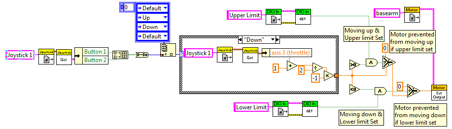
There are many ways to do limit switches the trick is to only disable the motor in the direction toward the limit switch and not the other direction. I've attached an image of how I would approach a dual limit switch problem.
· I would recommend that you move the motor set output vi outside the case structure and modify the output value based on the limit switch inputs
· You will need to create 2 digital inputs one for each limit switch in the Begin Vi
Hope this helps and I hope you have a great season.
Mark
02-07-2013 06:30 PM
Your picture is awesome thank you, but I have a question now if I move the set motor speed out of the case structure what should I do for the default case structures? Leave nothing in the case structure for the defaults? Thanks for all your help.
02-08-2013 09:27 AM
Hi BPtigers
The Motor speed needs to be outside the case structure so it will be written to every itteration of the loop that contains it.
Inside the motor vi is a saftey timer that makes sure the motor is continually updated aproximately every 200ms by default.
If the motor speed is not updated every 200 ms it will turn the motor off and assume the code is locked.
I would send a 0 for the default case if you want the motor to move only while the button is press.
You could also continually write the last value over and over using a shift register or feedback node.
This method however creates more issues to address not less
Good luck and thanks for letting me help.
Mark
02-09-2013 06:02 PM
Well I followed your picture and now my motor doesn't even move up or down. The jaguar light is a solid green when the code is enabled, but when I click and hold the up button or down button and push forward the throttle the green light doesn't change at all it appears like the motor is at 0 constantly, so I don't know if the pwn is bad or not? But here's my big question Assuming the code is right, it has to be the wiring, and assuming that the jaguar is wired right it has to be the limit switch wiring. My coach says that if we leave the limit switches unhooked altogether the limit should be false by default, because there is no limit switched plugged in. Is that true when a limit switch isn't plugged in it's naturally false in the code, or since the limit switch isn't plugged in the labview reads it as true. Also how is a limit switch suppose to be hooked in if we want it normally open. Thanks for all the help or if you do see an error in my coding let me know thanks.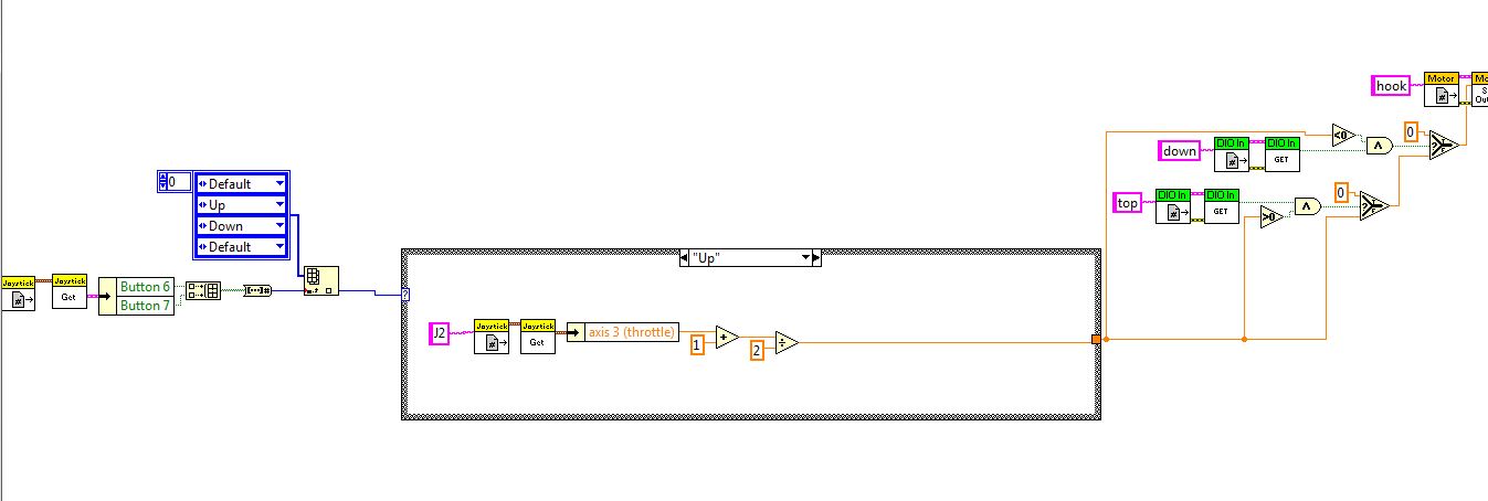
02-10-2013 02:02 PM
On another site it said to plug my limit switches into my jaguar instead? right now I have my limit switches plugged into my DIO on the digital sidecar, If I were to plug them into the jaguar instead is there any coding that I have to do or is it all done automatically by the jaguar, thanks
02-11-2013 09:35 AM
Hi BPtigers,
Sorry for the confusion
The wiring of DIO isn't as straight forward you would assume so let me try and clarify.
If you open the Help>>Find Examples and find the FRC Robotics folder in the NI Example Finder you will see a Digital folder that contains example VIs.
Open the Simple Digital Input.lvproj
When you Open the Simple digital Input.vi from the project and look at the front panel the diagram to the right explains how the digital input needs to be connected.
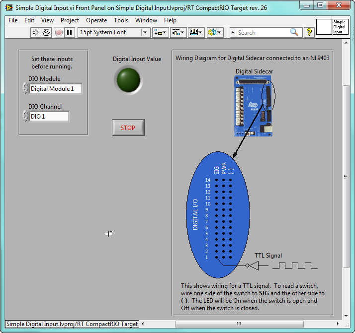
Electrically the Limit switch needs to be connected from SIG to [-]
The input will be in a high state by default until it is connected to [-]
So the code I showed before would only work if you wired a normally closed limit switch from SIG to [-]
and the switch would open at the limit position.
This wiring setup although not exactly straight forward is actually the best way to setup a limit switch. The reason why it is a good solution is that it forces the limit switch to be connected in order for the motor to run. If the limit switch gets unplugged or a wire gets cut it turns on the input indicating a limit condition.
As well as stopping the motor from moving when the limit switch is pressed it will also stop if the limit switch is not connected.
So if possible I would recommend connecting the limit switch Normally closed to [-] and Common to SIG.
If your limit switch does not have NC terminal then you will have to modify the code slightly to make it work.
Use a "not" function coming out of the Get Digital input vi to invert the boolean as shown

